Disc brakes

A technology of disc brakes and brake shafts, applied in the direction of brakes, brake types, axial brakes, etc., can solve problems such as jamming and difficulties, and achieve the effects of reducing manufacturing costs, eliminating jamming, and significant mechanical advantages

Active Publication Date: 2020-08-07
WABCO EURO BVBA SPRL
View PDF2 Cites 0 Cited by
  • Summary
  • Abstract
  • Description
  • Claims
  • Application Information

AI Technical Summary

Problems solved by technology

[0003] In the case of known disc brakes, that part of the guide plate, which is supposed to limit the mobility of the brake shaft, is located relatively deep inside the brake caliper, so that a precise handling for ensuring flawless function is difficult.
In addition, deformation of the brake parts involved, in particular the brake caliper, is effected due to the compression during braking, in particular in the sense that the gap between the brake shaft and the relevant section of the guide plate is reduced. , which can cause stuck

Method used


Image

  • Disc brakes
  • Disc brakes
  • Disc brakes

Examples


Embodiment Construction

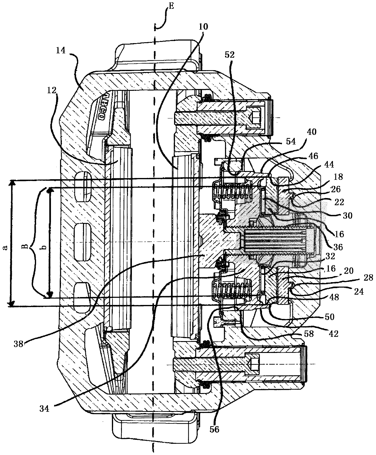
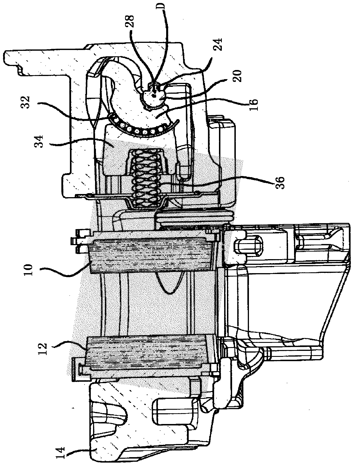
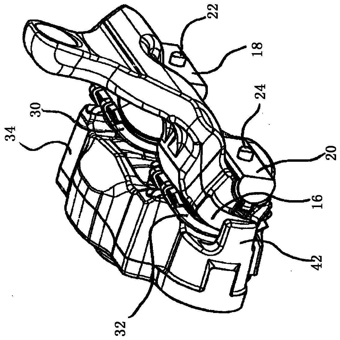
[0027] The pressure-side brake lining 10 and the rim-side brake lining 12 belong to the disk brake shown in the drawing and are located on opposite sides of the disk brake not shown in the drawing. superior. However, the main plane of the disc brake is drawn and provided with the reference E. Furthermore, the brake caliper 14 belongs to the disc brake, which is referred to as a sliding caliper. The brake shaft belonging to the hold-down device is designated with the reference numeral 16 . Its axis of rotation bears the reference D. On the side of the brake lining 10 facing away from the contact side, the brake shaft 16 is supported on the brake caliper 14 via sliding blocks 18 , 20 . The sliders each have a projection 22 , 24 which is inserted into a blind hole 26 or 28 .

[0028] On the side of the brake lining 10 facing the pressure side, the brake shaft 16 is supported on a pressure piece 34 via rotary bearings 30 , 32 . The pressure piece 34 is supported on the pressu...


PUM


Abstract

A disc brake, especially for commercial vehicles, the disc brake comprises: a brake disc; a brake shaft (16) whose axis of rotation is parallel to the main plane of the brake disc; relative to the brake disc The brake lining on the same side as the brake shaft (16); the pressing piece (34) between the brake shaft (16) and the brake lining; a degree restricting the movability of the pressing member relative to the brake disc in a direction parallel to the axis of rotation of the brake shaft; and a second restricting means (42) which restricts the brake shaft (16) relative to the brake disc to a predetermined second degree Mobility in a direction parallel to the axis of rotation of the brake shaft, wherein the brake shaft presses the pressure piece and thus also the brake lining against the brake disc during actuation. The second limiting device has a first stop (32) on the pressure piece (34) and a second stop on the brake shaft cooperating with the first stop in the sense of limiting the movability .

Description

technical field [0001] The invention relates to a disc brake, especially a disc brake for a commercial vehicle. The disc brake comprises: a brake disc, a brake shaft (whose rotation axis is parallel to the main plane of the brake disc), relative to the brake A brake pad on the same side as the brake shaft for the disc, a pressure piece between the brake shaft and the brake pad, a first limiting device (which limits the pressure piece to a predetermined first degree relative to the braking movability of the brake shaft in a direction parallel to the axis of rotation of the brake shaft) and second limiting means (which limit the movement of the brake shaft relative to the brake disc in a direction parallel to the axis of rotation of the brake shaft to a predetermined second degree) movability), wherein the brake shaft presses the pressure piece and thus the brake lining against the brake disc during actuation. Background technique [0002] A disk brake of the type mentioned a...

Claims


Application Information

Patent Timeline
Patent Type & Authority Patents(China)
IPC IPC(8): F16D65/18
CPCF16D65/18F16D2121/14F16D2125/26F16D2125/32F16D2125/64B60T1/06B60T13/12F16D55/22
Inventor 汉斯-克里斯蒂安·容曼彼得·莫泽维塔利·舍雷尔拉尔夫·格罗斯科普夫
Owner WABCO EURO BVBA SPRL
Why Eureka
Try Eureka