Decorative plate connection structure
A technology for connecting structures and decorative panels, applied in building construction, covering/lining, construction, etc., can solve the problems of broken rivets, inconvenient disassembly and assembly, and achieve the effects of avoiding internal forces, saving installation time, and improving adjustment capabilities
- Summary
- Abstract
- Description
- Claims
- Application Information
AI Technical Summary
Problems solved by technology
Method used
Image
Examples
Embodiment 1
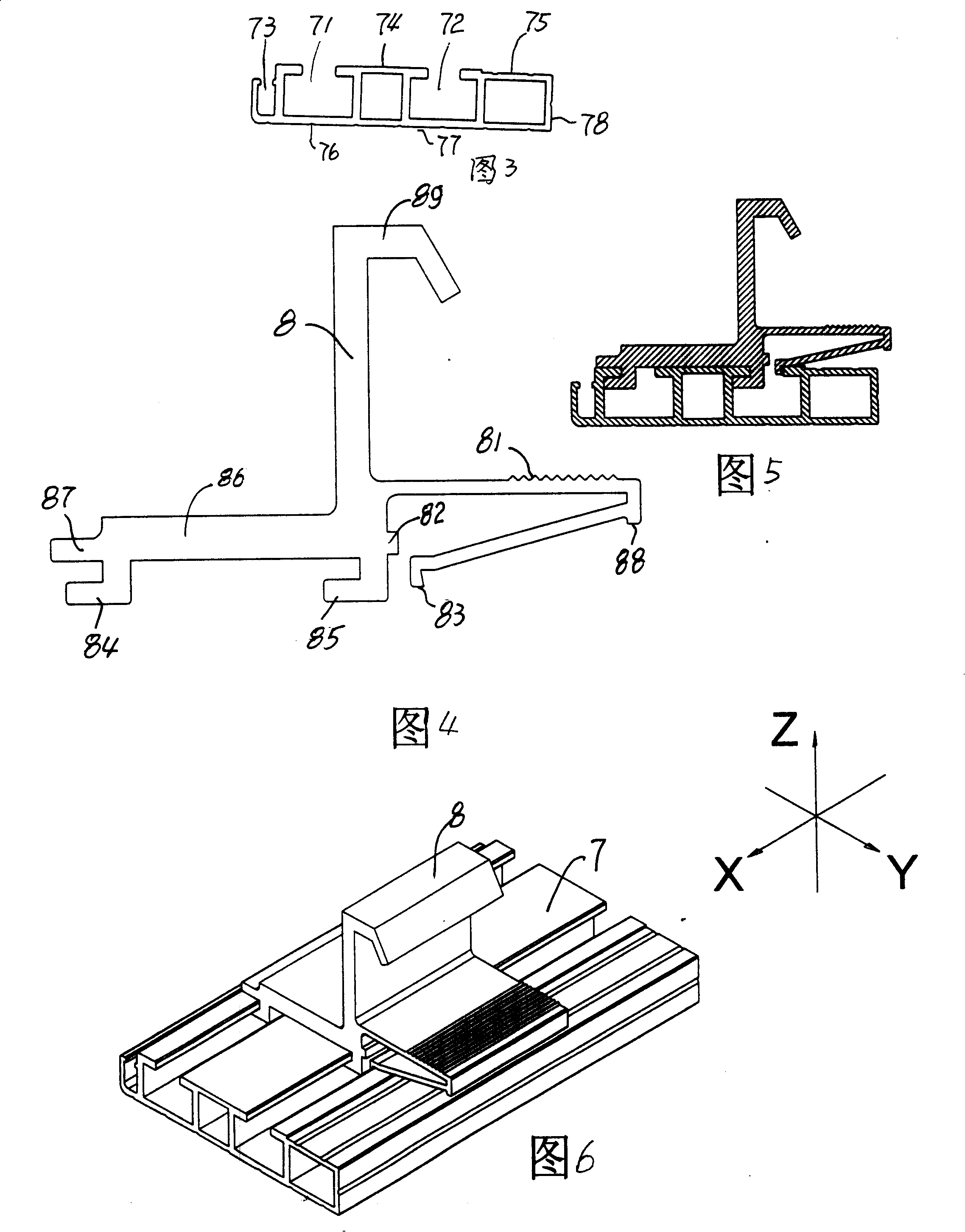
[0027] Embodiment 1, see accompanying drawing 3~6:
[0028] A decorative panel connection structure, consisting of a connecting piece 8 and a profile 7;
[0029] There are two hooks 84 and 85 in the same direction on the lower part of the connector 8, and there is a space between the two hooks; there is an integral elastic lock hook 83 on the opposite side of the hook bending direction; The surface of the elastic lock hook has corrugated grain 81, and its effect is to improve the feel when installing; the body plane with corrugated grain is higher than the body plane 86 with the hook; a grab 84 is located on the other side of the connector There is a protruding edge 87 on the top of the protruding edge 87, which forms a slot with the hook 84, and is stuck on the profile slot 71; the function of the protruding edge 87 is to maintain the accurate fit between the connector and the profile slot, so that the connector Glides smoothly in the card slot. There is a small flange 88 a...
Embodiment 2
[0033] Embodiment 2, see accompanying drawing 7~9.
[0034] The connecting piece is a wall decoration board connecting piece 9 with a hook at its front, and the height of the hook is lower than that of the first embodiment. The hook of the wall decorative panel connector 9 is located above the front hook 84, and the longitudinal plate of the wall decorative panel connector hook has a threaded hole 91; other structures are the same as in Embodiment 1; the longitudinal plate of the connector 9 hook Have threaded hole 91 on; Its effect is to install the screw of a position adjustment.
[0035] The structure is suitable for the installation of interior wall decorative panels, and the hooks are matched with the corresponding wall joists.
Embodiment 3
[0036] Embodiment 3, see attached Figure 10-11 :
[0037] The connecting piece is a decorative board hanging connecting piece 10 , its upper surface is flat, and its upper surface extends in the opposite direction to the elastic locking hook, and the lower end of the extension part has a positioning flange 101 . The hanger has no hook structure. The positioning flange 101 can be embedded in the slot of the pre-installed profile of the adjacent plate, plays a positioning role, and can control the size of the seam of the plate. Other structures are with embodiment 1.
[0038] The feature of this structure is that the overall shape is similar to an insert or patch, which can be placed (inserted) on the back of the adjacent plate when the plates are spliced together.
[0039] This structure is applicable to the installation of ceiling boards or interior wall decoration boards.
PUM
 Abstract
Description
Claims
Application Information
 - R&D
- Intellectual Property
- Life Sciences
- Materials
- Tech Scout
- Unparalleled Data Quality
- Higher Quality Content
- 60% Fewer Hallucinations
Browse by: Latest US Patents, China's latest patents, Technical Efficacy Thesaurus, Application Domain, Technology Topic, Popular Technical Reports.
© 2025 PatSnap. All rights reserved.Legal|Privacy policy|Modern Slavery Act Transparency Statement|Sitemap|About US| Contact US: help@patsnap.com


