Fastener

A technology for fasteners and components, applied in the direction of rivets, etc., can solve problems such as inability to apply large clamping force and weakening of clamping force

Active Publication Date: 2008-07-02
PIOLAX CO LTD +1
View PDF7 Cites 2 Cited by
  • Summary
  • Abstract
  • Description
  • Claims
  • Application Information

AI Technical Summary

Problems solved by technology

[0004] Therefore, although in the case of the fasteners of the prior art, the advantage of being able to simply fix the trim panel and the body panel is achieved, on the other hand, in the state where the trim panel is fixed, since the trim panel and the body panel pass through The relationship of the flange portion of the grommet made of synthetic resin and the divided leg members clamped from the inside and the outside, obviously, the clamping force for clamping the body panel to the hole edge of the connection hole is weakened, therefore, cannot apply high clamping force

Method used


Image

  • Fastener
  • Fastener
  • Fastener

Examples


Embodiment 1

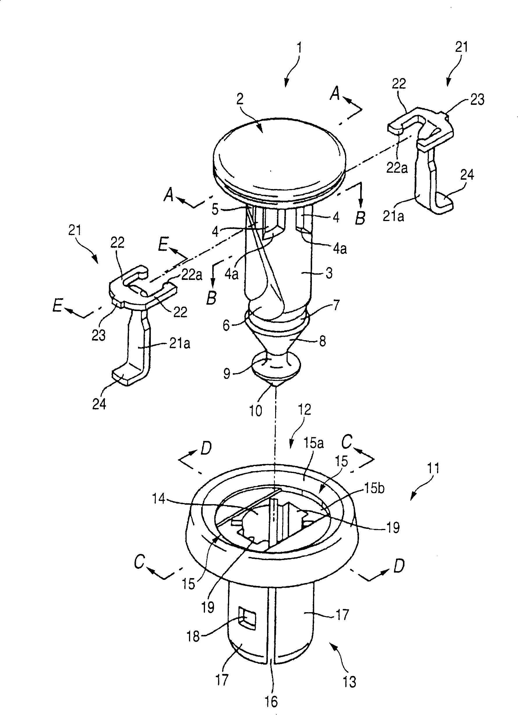
[0057] The present invention is described based on the following preferred embodiments, different from the fasteners of the prior art, such as figure 1 As shown, the fastener according to this embodiment includes three parts, namely, a pin 1 made of synthetic resin, a grommet 11 made of synthetic resin, and a clamping member 21 made of metal, and its It is characterized in that each part 1, 11, 21 adopts the following structure. In addition, for clamp members made of metal, the clamp members 21 are used in a paired relationship.

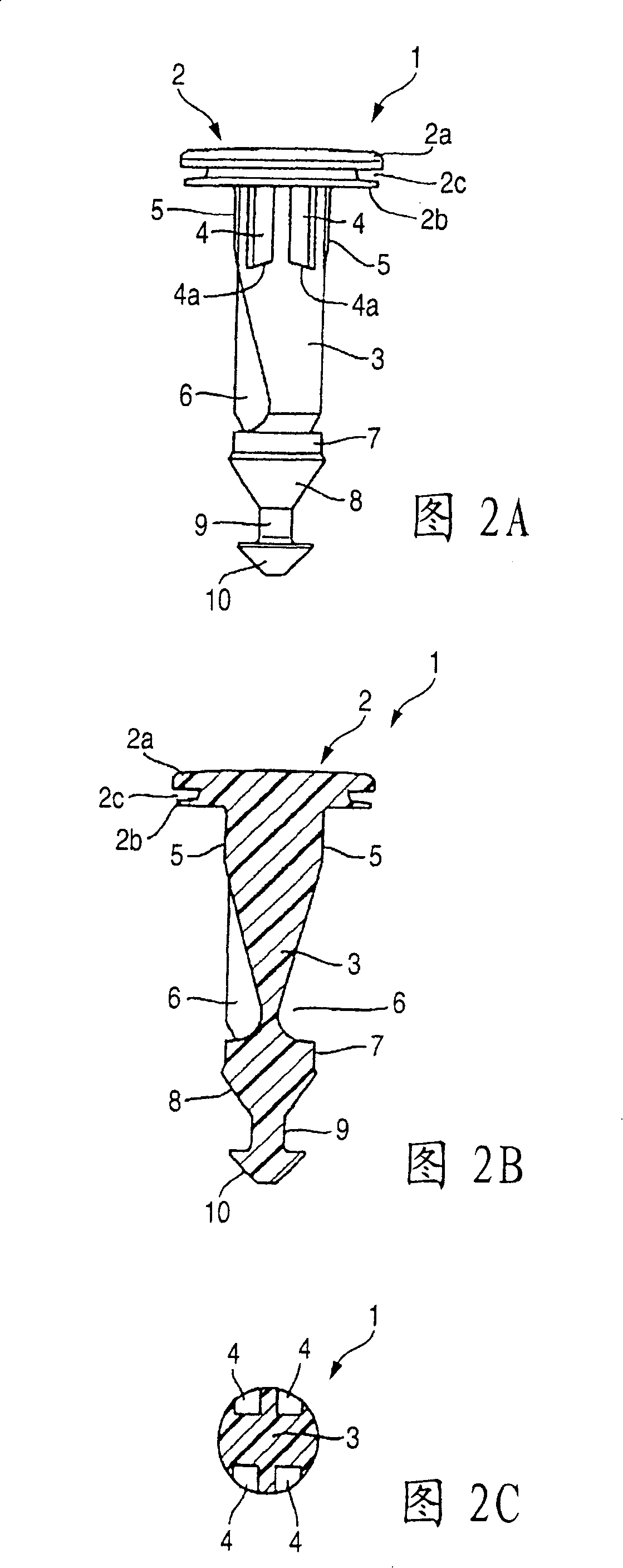
[0058] Therefore, firstly, a pin 1 made of synthetic resin will be described, and as also shown in FIGS. It includes a thick-walled upper plate 2a and a thin-walled lower plate 2b, and is separated by a ring-shaped insertion groove 2c so that the front end of the tool is inserted between the upper plate 2a and the lower plate 2b, and the rear rod 3 member Consisting of a structure in which support grooves 4 are formed on one side of the upper side ...

Embodiment 2

[0074] The fastener of the second embodiment is explained below, although the structure of the second embodiment basically follows the structure of the above-mentioned first embodiment, the difference between the two lies in the structure in which from the shank 3 of the pin 1 A pair of anti-movement walls 30 in a state parallel to each other protrude integrally from both side edges of the two accommodating chambers 6 formed on the side, on the sides of the support groove 4 of the lower plate 2b constituting the head 2 of the pin 1 The peripheral edge existing on the top is cut by a notch 31 , and a protruding stripe 32 parallel to the edge of the notch 31 is provided on the upper plate 2 a at a position directly above the edge of the notch 31 .

[0075] Therefore, according to the second embodiment, by the presence of the aforementioned pair of movement preventing walls 30, when the clamping member 21 is supported by the shank portion 3 of the pin 1 and inserted into the cylin...

Embodiment 3

[0079] In the following, the present invention will be described in detail according to preferred embodiments, and the difference from the fasteners of the background art is, for example Figure 11 As shown, the fastener of this embodiment includes three parts: a pin 101 made of synthetic resin, a grommet 111 made of synthetic resin, and a clamping member 121 made of metal, characterized in that Each section 101, 111 and 121 adopts the following structure. In addition, as for the clamp member made of metal, the clamp member 121 is formed of a low-rigidity elastic metal plate and used in pairs.

[0080] Therefore, first, the explanation starts from the pin 101 made of synthetic resin, as Figure 12 As shown, the pin 101 is provided with a disc-shaped head 102 and a cylindrical stem 103. Specifically, the latter stem 103 is structured as follows, wherein a pair of opposite sides of the upper part are formed. The pressing surface 104 is used to press the outwardly guiding clamp...


PUM


Abstract

A fastener including a pin, a grommet and a pinching member, wherein the pin includes a head portion and a shaft portion, the grommet includes a flange portion and a barrel portion, and the pinching member includes an inward directed support arm and an outward directed pinching piece, the head portion includes a support portion for supporting the inward directed support arm of the pinching member, a containing chamber for containing a side of the outward directed pinching piece of the pinching member to direct in a direction of a center of the shaft portion and a press face for pressing outward the outward directed pinching piece of the pinching member at the shaft portion of the pin and forming an opening window for putting in and out the outward directed pinching piece of the pinching member at the barrel portion of the grommet.

Description

technical field [0001] The present invention relates to a fastener for fastening interior or exterior parts or the like of an automobile to a predetermined body panel. Background technique [0002] Although not specifically stated, this prior art fastener consists of two parts, a pin made of synthetic resin and a grommet made of synthetic resin, the former pin member being provided with a disc-shaped head part and a cylindrical-shaped stem part hanging from the lower surface of the head, the stem part is formed with a large-diameter groove and a small-diameter groove at its side along the axial direction, and the latter grommet member is provided with a disc-shaped A flange portion and a cylinder portion in the shape of a cylinder hanging down from the lower surface of the flange portion, the flange portion is formed with an opening for inserting the shank of the pin at its center, and the cylinder portion is constructed so that it The peripheral wall is divided into a plur...

Claims


Application Information

Patent Timeline
Patent Type & Authority Patents(China)
IPC IPC(8): F16B19/10
Inventor 筱崎伸哉田中启文涩谷明宏望冈保雄
Owner PIOLAX CO LTD
Why Eureka
Try Eureka