
Split-cycle engine with dwell piston motion

An engine, piston technology, applied in the field of split-cycle engines

Inactive Publication Date: 2008-07-09
SKADERI GRUP LLC
View PDF6 Cites 0 Cited by
  • Summary
  • Abstract
  • Description
  • Claims
  • Application Information

AI Technical Summary

Problems solved by technology

[0012] The problem is that the full thermodynamic efficiency of a typical four-stroke engine 10 is only about one-third (1 / 3)

Method used


Image

  • Split-cycle engine with dwell piston motion
  • Split-cycle engine with dwell piston motion
  • Split-cycle engine with dwell piston motion

Examples


Embodiment Construction

[0041] I. Overview

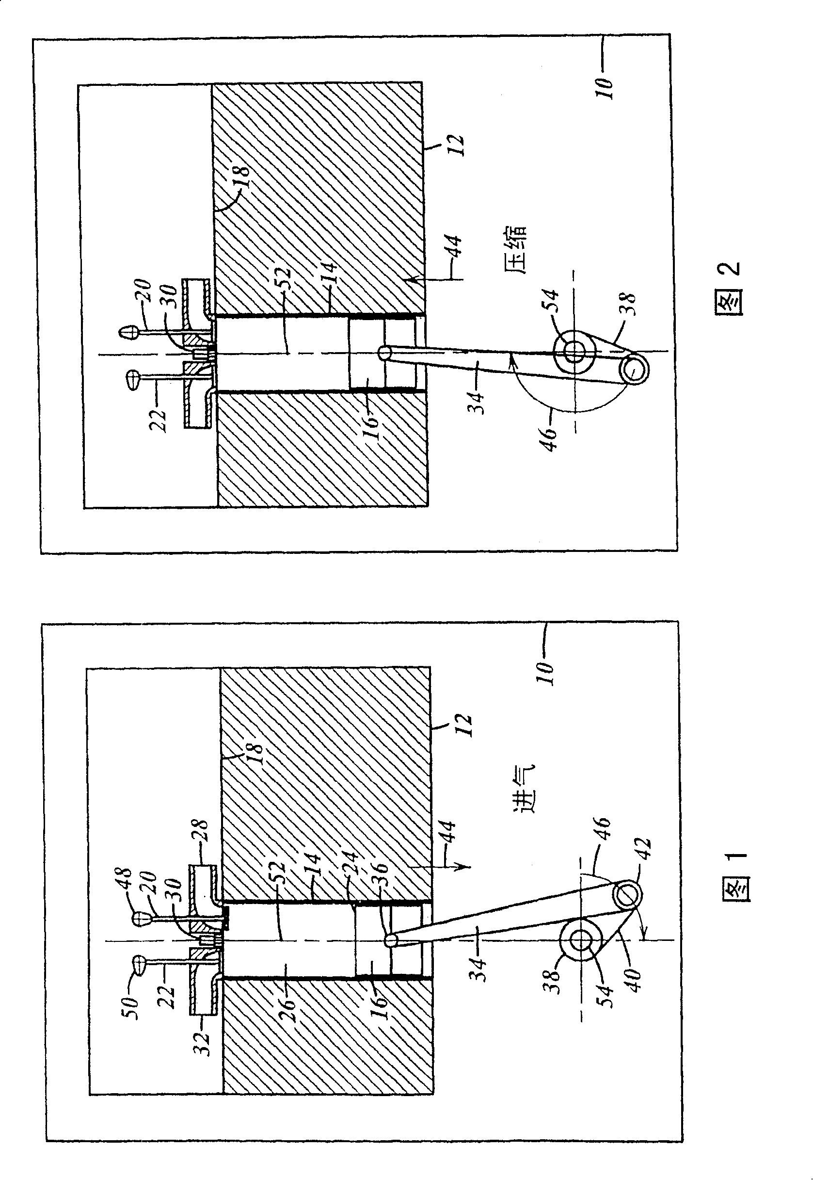
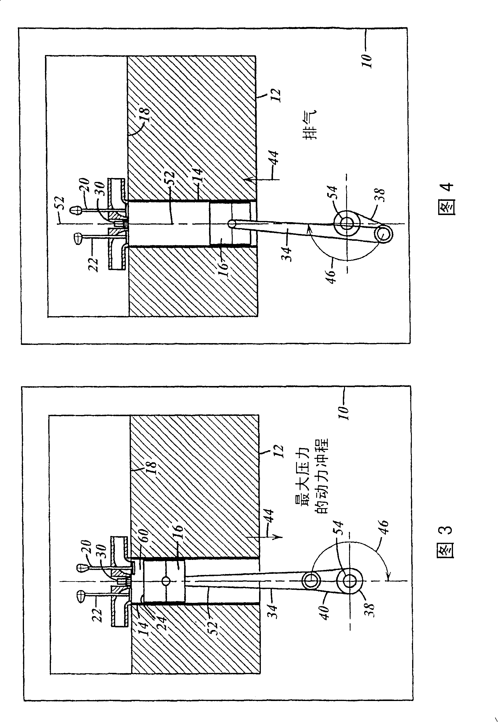
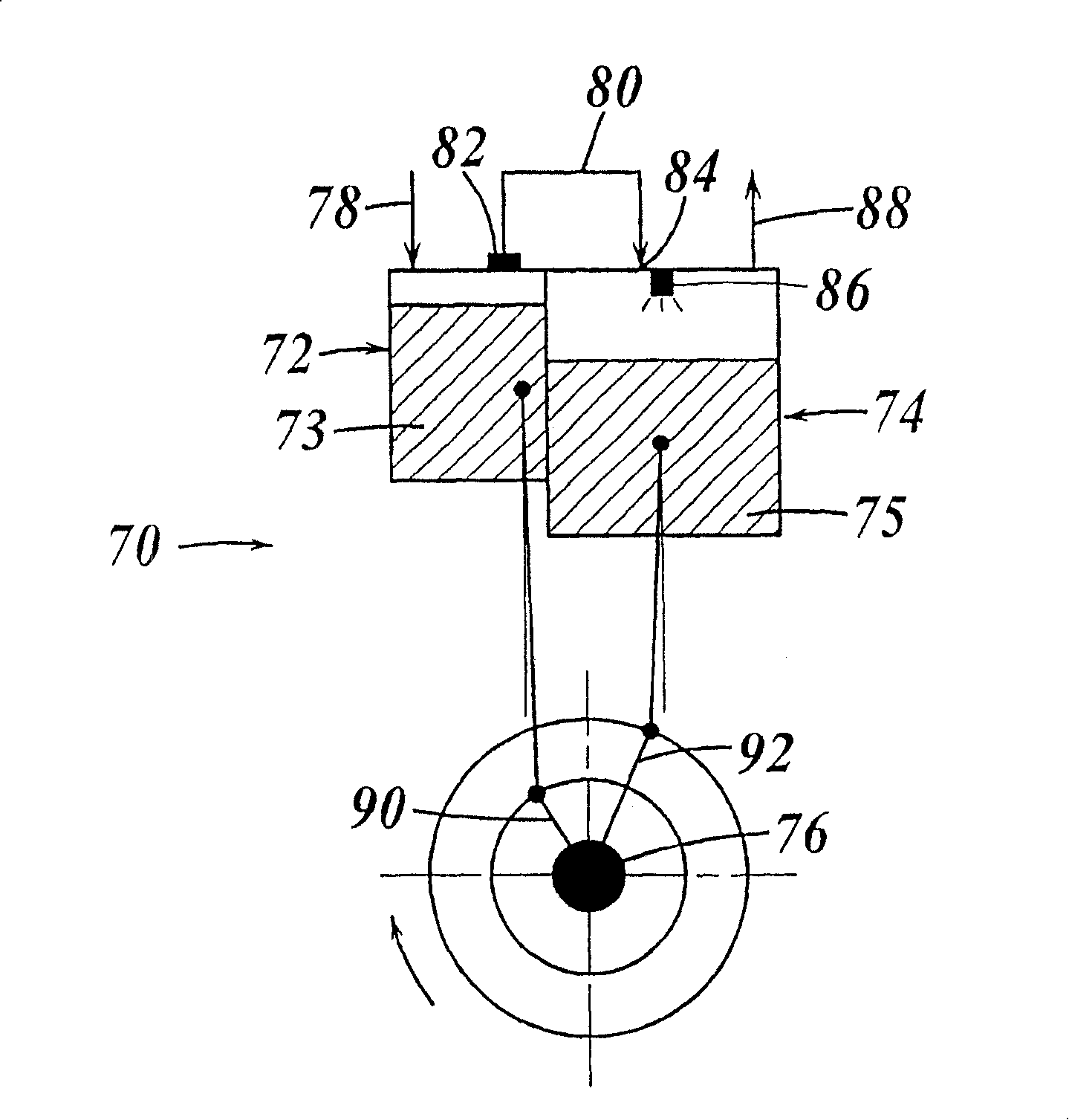
[0042] Scuderi Group Commissions Southwest Research Institute in San Antonio, Texas (SwRI ) to perform a paired computerized study. The first study involved constructing a computerized model representing various split-cycle engine embodiments compared to a computerized model of a conventional internal combustion engine with the same captured mass per cycle. The final report of the first study (SwRI presented on 24 June 2003 Project No. 03,05932, entitled "Evaluation of the Split-Cycle Four-Stroke Engine Concept"), is hereby incorporated by reference in its entirety. The first study led to US Patent Application No. 10 / 864748, filed June 9, 2004, by Branyon et al., entitled "Separated Cycle Four-Stroke Engine," the entire contents of which are incorporated herein by reference. The first study identified specific parameters (e.g., compression ratio, expansion ratio, diverter valve duration, phase angle, and overlap between diverter valve activity and c...


PUM


Abstract

An engine includes a crankshaft having a crank throw, the crankshaft rotating about a crankshaft axis. A compression piston is slidably received within a compression cylinder and operatively connected to the crankshaft such that the compression piston reciprocates through an intake stroke and a compression stroke of a four stroke cycle during a single rotation of the crankshaft. An expansion piston is slidably received within an expansion cylinder. A connecting rod is pivotally connected to the expansion piston. A mechanical linkage rotationally connects the crank throw to the connecting rod about a connecting rod / crank throw axis such that the expansion piston reciprocates through an expansion stroke and an exhaust stroke of the four stroke cycle during the same rotation of the crankshaft. A path is established by the mechanical linkage which the connecting rod / crank throw axis travels around the crankshaft axis. The distance between the connecting rod / crank throw axis and crankshaft axis at any point in the path defines an effective crank throw radius. The path includes a first transition region from a first effective crank throw radius to a second effective crank throw radius through which the connecting rod / crank throw axis passes during at least a portion of a combustion event in the expansion cylinder.

Description

[0001] Cross References to Related Applications [0002] This application claims priority to US Provisional Application No. 60 / 489,893, entitled "Cam Angle Piston Motion for Split-Cycle Engines," filed July 23, 2003, the entire contents of which are incorporated herein by reference. field of invention [0003] The invention relates to an internal combustion engine. More specifically, the present invention relates to a split-cycle engine having a pair of pistons, one for the intake and compression strokes and the other for the expansion (or drive) and discharge strokes, each of the four The stroke is completed in one crankshaft revolution. The mechanical linkage for operatively connecting the expansion piston to the crankshaft provides a very slow period of motion during a portion of the combustion cycle relative to the downward movement of the same piston pivotally connecting the connecting rod to the crankshaft through a fixed pin connection. The piston moves downward. Ba...

Claims


Application Information

Patent Timeline
Patent Type & Authority Patents(China)
IPC IPC(8): F02B33/22F02B75/02F02B75/34
CPCF02B41/08F02B75/02F02B75/34F02B33/22F02B2275/36F02B33/02F02B75/00
Inventor 萨尔瓦托雷·C·斯库德里大卫·P·布拉扬
Owner SKADERI GRUP LLC
Features
  • Generate Ideas
  • Intellectual Property
  • Life Sciences
  • Materials
  • Tech Scout
  • Unparalleled Data Quality
  • Higher Quality Content
  • 60% Fewer Hallucinations
Learn More