Controlling means for ship stabilizing gear

A technology of anti-rolling device and control method, which is applied in the field of fin stabilizers, can solve the problems of undiscovered, no remote-driven equipment, troublesome operation, etc., and achieve the effects of improving safety, excellent working effect, and preventing cargo from collapsing

Active Publication Date: 2008-07-23
无锡市东锦宏投资管理有限公司
View PDF11 Cites 1 Cited by
  • Summary
  • Abstract
  • Description
  • Claims
  • Application Information

AI Technical Summary

Problems solved by technology

[0020] However, most of the existing technologies do not have long-distance driving equipment. At this time, the crew operates manually. Therefore, the F/S with high anti-rolling efficiency is the main method, and ART is used as the low speed state of the ship.

Method used


Image

  • Controlling means for ship stabilizing gear
  • Controlling means for ship stabilizing gear
  • Controlling means for ship stabilizing gear

Examples


Embodiment Construction

[0037] The embodiments of the present invention will be described in conjunction with embodiments and with reference to the drawings.

[0038] Moreover, as described above, since the working principle of the lift-type anti-rolling device F / S12 and the rudder anti-rolling device 13 are the same, this specification will take the F / S12 as an example for description, but even if the F / S The embodiment in which S12 is replaced with the rudder anti-rolling device 13 is also suitable.

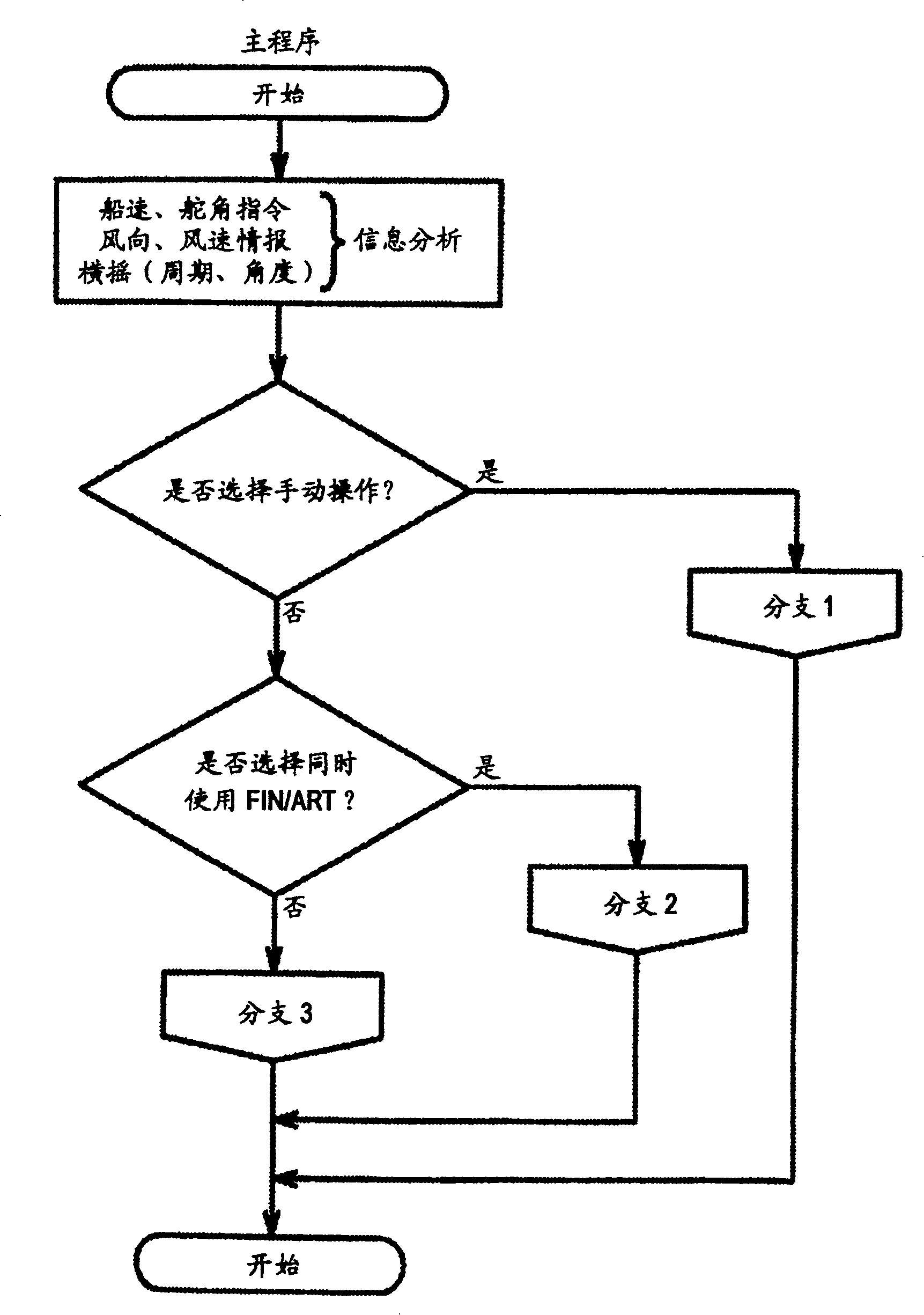
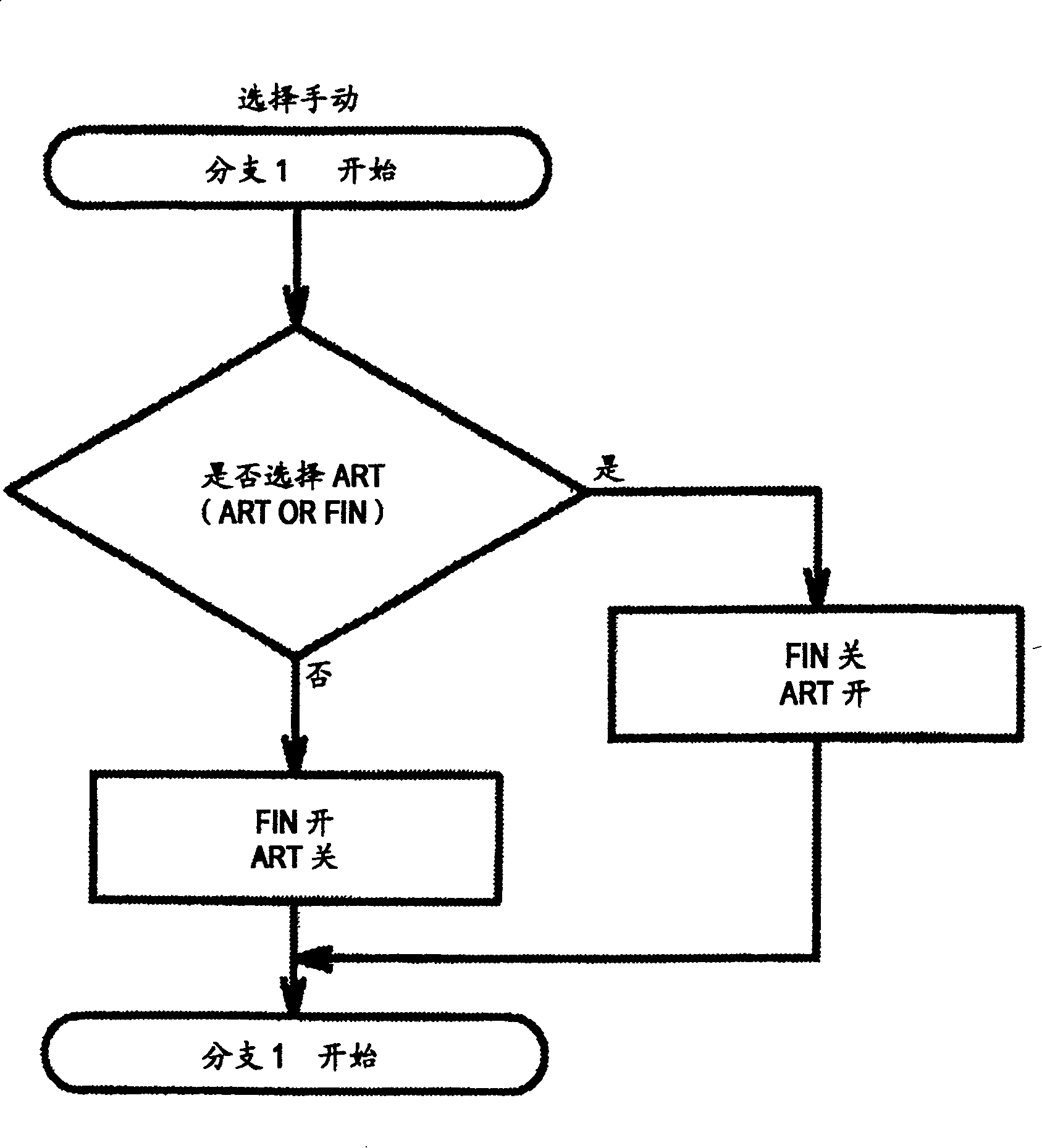
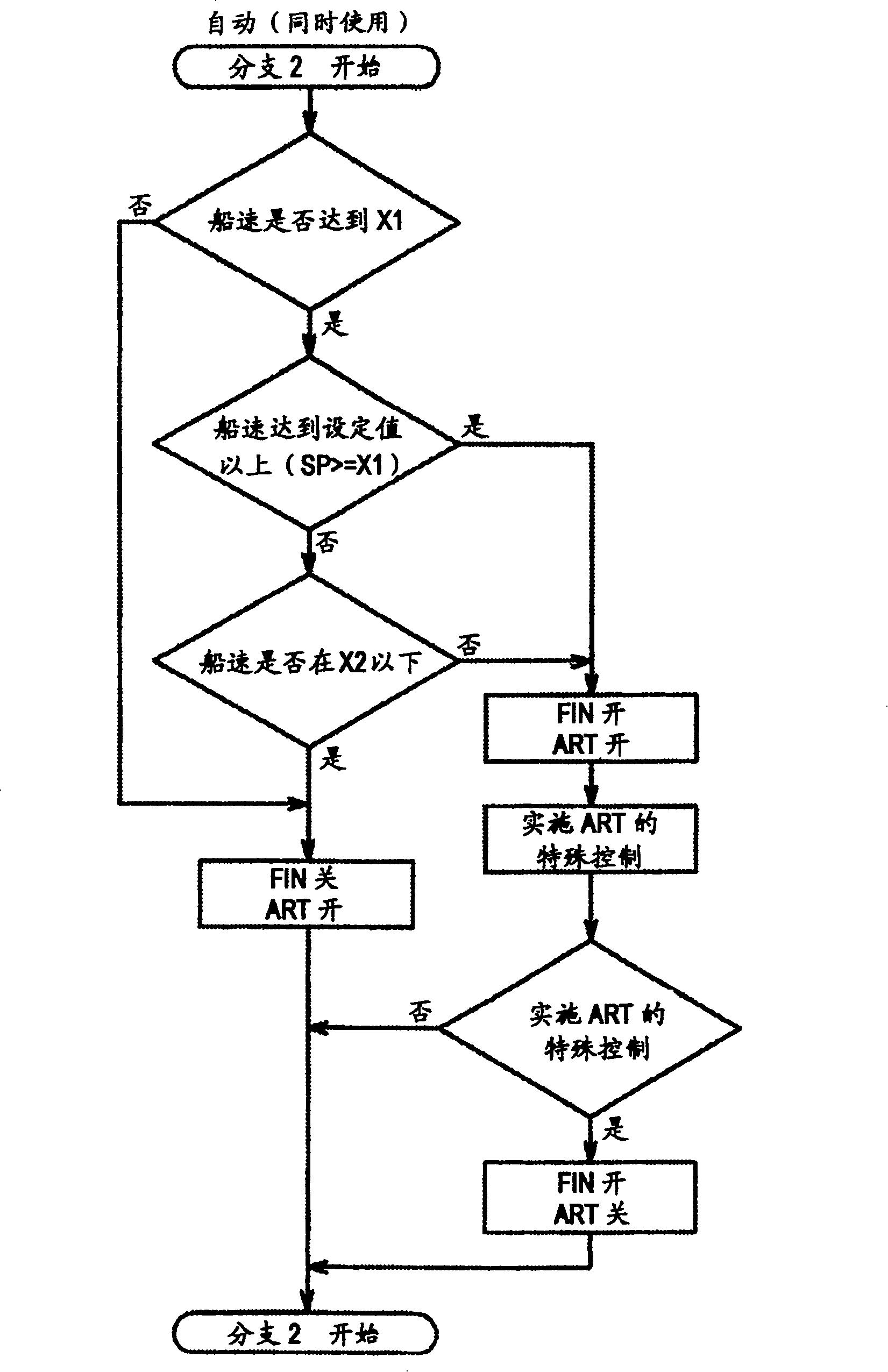
[0039] What the present invention provides is a control method that can be used when F / S12 and ART9 are set at the same time, and according to preset conditions, through automatic switching, priority use of F / S12 and ART9 One of ART9. Therefore, the anti-rolling structure of F / S12 and ART9 and their respective control methods are not directly related to the present invention. Therefore, regarding this aspect, especially ART9, use citation example-1~ The example of Example-4 is cited, and the description i...


PUM


Abstract

To provide a control method for a rocking reducing device in which a buoyancy type rocking reducing device (fin stabilizer or rudder swing reducing device) of automatic control type and a U-pipe passive type swing-reducing water tank device (ART) of automatic control type are installed in line and used, capable of allowing the two devices to work with their merits efficiently, complementing each other's demerits, and performing an automatic control so that the liquid of ART does not ill influence the F/S (fin stabilizer). The buoyancy type rocking reducing device 14 of automatic control type and a passive type swing-reducing water tank 15 of automatic control type are installed in line, and a control part 4 capable of making remote control of the two devices is installed on a bridge or in an apparatus monitoring room. A system is constructed so that the two devices 14 and 15 can be selected through changing-over by an automatic or a manual operation. In the case of automatic selection, priority for use is given to the device meeting the preset conditions on the basis of the vessel information fundamentally, and the automatic control is conducted in such a manner that the other device does not ill influence the selected device. (C)2004,JPO&NCIPI.

Description

Technical field [0001] The present invention relates to a fin stabilizer, and a control method when a lift-type and passive-type anti-roll tank (limited to U-shaped tube type) is installed and used at the same time, such as a fin stabilizer or a rudder stabilizer device, especially automatic selection The above-mentioned anti-rolling device, which is most suitable for the ship's speed or other conditions during sailing, and a method of controlling the anti-rolling device of a ship. Background technique [0002] In the past, fin stabilizers (hereinafter also referred to as F / S) or rudder anti-rolling devices were actually used to use the FIN (wing plate) protruding out of the hull or the lift generated on the rudder surface as the anti-rolling moment. Lift type and U-tube type passive anti-rolling tanks (hereinafter also referred to as ART) that use the natural law of liquid flowing from high to low are used as ship's anti-rolling devices. The device can obtain sufficient anti-rol...

Claims


Application Information

Patent Timeline
IPC IPC(8): B63B39/03B63B39/06B63B43/06
Inventor 松村纪孝
Owner 无锡市东锦宏投资管理有限公司
Why Eureka
Try Eureka