Light conducting plate and back light module

A backlight module and light guide plate technology, which is applied in optics, nonlinear optics, instruments, etc., can solve problems such as unsatisfactory outgoing light, uniform outgoing light, and inability to adapt to different light sources, so as to achieve improved brightness, uniform outgoing light, and light output. high brightness effect

Inactive Publication Date: 2008-07-23
HONG FU JIN PRECISION IND (SHENZHEN) CO LTD +1
View PDF4 Cites 0 Cited by
  • Summary
  • Abstract
  • Description
  • Claims
  • Application Information

AI Technical Summary

Problems solved by technology

However, the brightness of the emitted light alone cannot meet the requirements of the current high-brightness backlight module, and the angle between the sides of the bottom surface 11, the groove 12, and the bottom surface cannot be changed correspondingly with the distance from the light source to make the emitted light more uniform. , nor can it adapt to the needs of different light sources

Method used


Image

  • Light conducting plate and back light module
  • Light conducting plate and back light module
  • Light conducting plate and back light module

Examples


Embodiment Construction

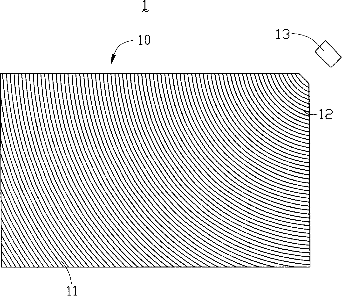
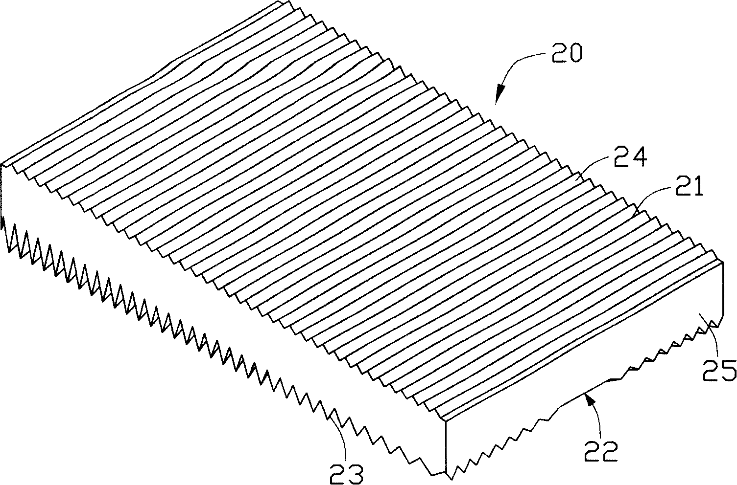
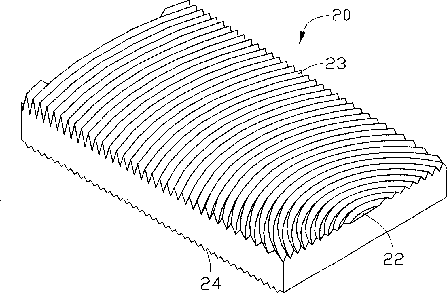
[0023] Please also refer to figure 2 , image 3 , Figure 4 , Figure 5 and Image 6 , is the first embodiment of the light guide plate of the present invention. The light guide plate 20 includes a light incident surface 25, a light exit surface 21 adjacent to the light incident surface 25, and a bottom surface 22 opposite to the light exit surface 21; -6 ~10 -8 The groove 23 is an arc-shaped groove 23. The groove 23 is a continuous concentric structure, and its center 26 is set in the middle of the light incident surface 25 side. The groove 23 and the light guide plate 20 are integrally injection molded, and its cross section is V-shaped. , including two sides 231, 232, the angle α between the side 232 facing the light incident surface 25 and the bottom surface 22 gradually increases as the distance between the groove 23 and the light incident surface 25 increases; the light exit surface 21 also includes A plurality of V-shaped grooves 24, the grooves 24 of the light-e...


PUM


Abstract

The invention is a light guide plate, comprising a light incident surface, a light outgoing surface adjacent to the light incident surface and a bottom surface opposite to the light outgoing surface, where the bottom surface comprises a plurality of arc grooves and the light outgoing surface also comprises a plurality of grooves.

Description

【Technical field】 [0001] The invention relates to a light guide plate and a backlight module. 【Background technique】 [0002] Backlight modules are widely used in display devices, such as liquid crystal displays, mobile phones, etc., but many display devices are not self-illuminating displays, and are mainly realized by controlling the passage or non-passage of light emitted by external light sources, so corresponding backlight or front lights are required. Light module, the backlight or front light module can guide the light emitted by the external light source to the display panel, so as to realize the display function. [0003] With the popularity of mobile phones, the requirements for backlight modules used in mobile phones are also getting higher and higher, mainly regarding the display brightness requirements of mobile phones, while the requirements for viewing angle range are relatively low. [0004] see figure 1 , is a prior art backlight module disclosed in U.S. P...

Claims


Application Information

Patent Timeline
Patent Type & Authority Patents(China)
IPC IPC(8): G02F1/13357G02F1/1335
Inventor 余泰成吕昌岳陈杰良
Owner HONG FU JIN PRECISION IND (SHENZHEN) CO LTD
Why Eureka
Try Eureka