
Optical pointing device with shading element

An optical pointing, photosensitive element technology, applied in the input/output process of data processing, instruments, electrical digital data processing, etc., can solve the user's troubles, increase the complexity and manufacturing cost of the laser optical mouse, and cannot limit Problems such as the sensing range of the photosensitive element 322 to achieve the effect of eliminating the mechanical structure

Active Publication Date: 2008-07-30
PIXART IMAGING INC
View PDF5 Cites 0 Cited by
  • Summary
  • Abstract
  • Description
  • Claims
  • Application Information

AI Technical Summary

Problems solved by technology

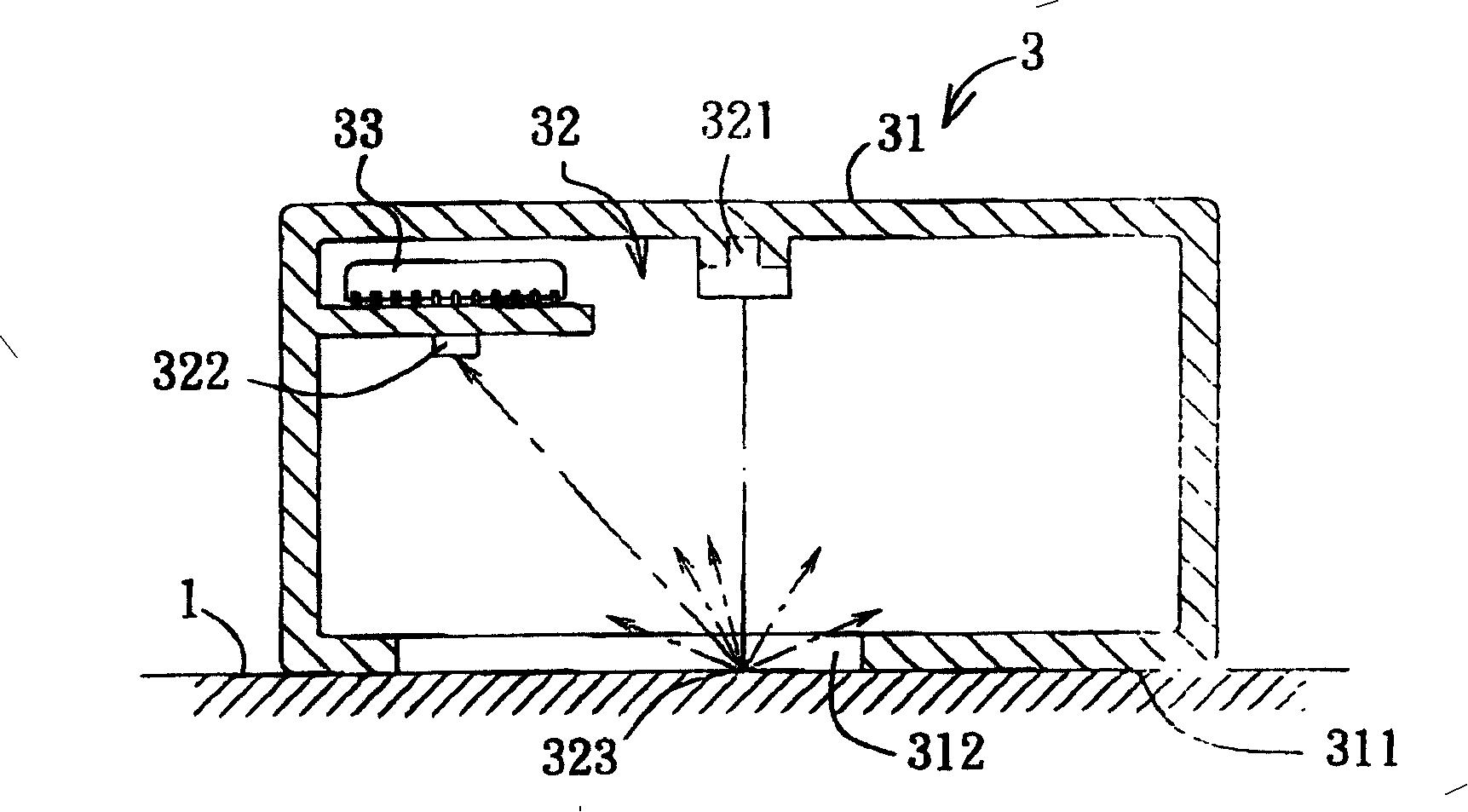
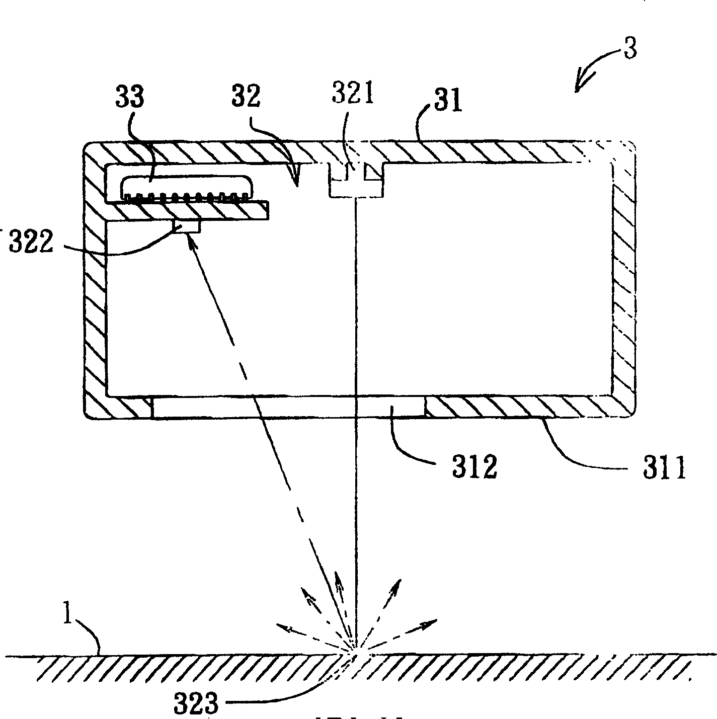
In other words, the existing laser optical mouse 3 cannot limit the sensing range of the photosensitive element 322, causing troubles for users to use the laser optical mouse 3; or an additional detection bottom surface 311 and reference surface 1 need to be added. The relative distance detection device increases the complexity and manufacturing cost of the laser optical mouse 3

Method used


Image

  • Optical pointing device with shading element
  • Optical pointing device with shading element
  • Optical pointing device with shading element

Examples


Embodiment Construction

[0024] The aforementioned and other technical contents, features and functions of the present invention will be clearly presented in the following detailed description of two preferred embodiments with reference to the drawings.

[0025] Before the present invention is described in detail, it should be noted that in the following description, similar elements are denoted by the same reference numerals.

[0026] refer to Figure 4 In the first preferred embodiment of the present invention, the optical pointing device 4 with a light-shielding element indicates the position by measuring the relative translation of a reference surface 5, such as a pointer for controlling an operating system (not shown). The reference surface 5 can be a plane provided by a mouse pad, or other available planes. However, in practice, the reference surface 5 can also be the outer surface of a trackball. The optical pointing device 4 includes a casing 6 , an optical unit 7 , and a processing unit 8 ....


PUM


Abstract

The invention discloses an optical directional device with a light-screening component for indicating position by measuring relative translation of a reference surface. The inventive device comprises an optical unit and a process unit for processing optical signal. The optical unit includes a light-emitting component for forming a light dot on a reference surface, a light sensing component, and a light-screening component. The light-screening component has a light-penetrated hole and matches with the light sensing component to decide measurement range, which make the lighting point gets far away from the measurement range when the optical directional device gets far away from the reference surface.

Description

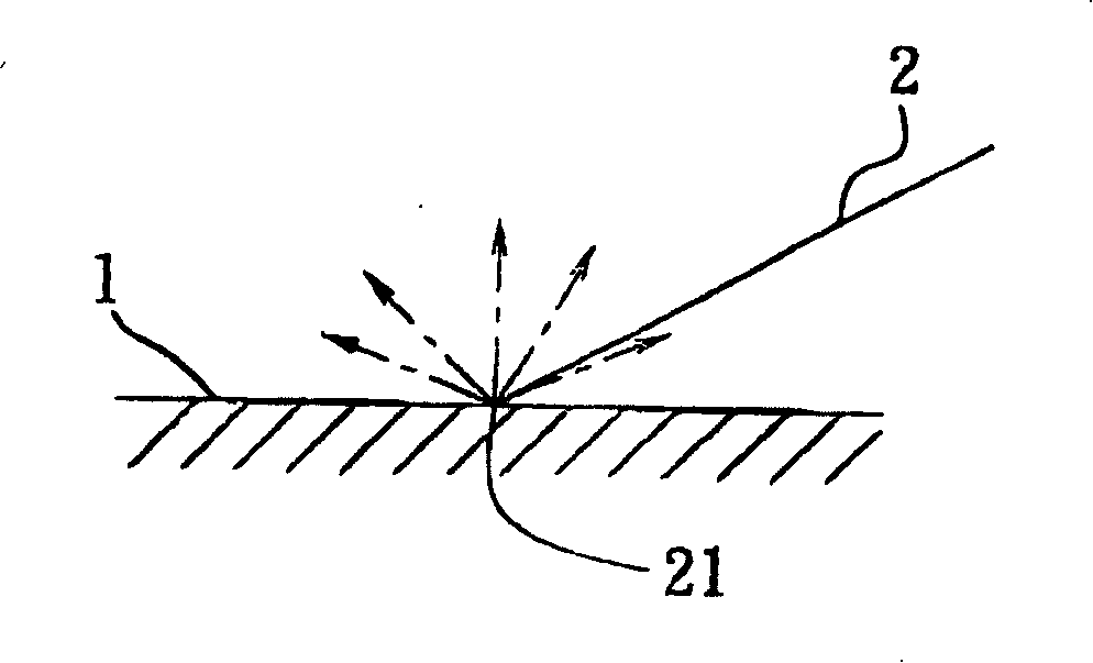
technical field [0001] The invention relates to a pointing device, in particular to an optical pointing device with a light shielding element. Background technique [0002] Such as figure 1 As shown, when a laser beam 2 irradiates a reference surface 1, since the laser beam 2 is coherent light, the scattered light meets and interferes in front of the bright spot 21 formed by the laser beam 2, so that part of the scattered light The brightness is enhanced, and the brightness of part of the scattered light is weakened, forming three-dimensional spots with different sizes, shapes, and brightness in all directions. These three-dimensional spots are called speckles. This randomly distributed speckle structure is called a speckle pattern. The speckle distribution of the speckle field is related to the fluctuation and roughness of the reference surface 1 , so as the laser beam 2 irradiates on different positions of the reference surface 1 , the speckle distribution of the speckle...

Claims


Application Information

Patent Timeline
Patent Type & Authority Patents(China)
IPC IPC(8): G06F3/033
Inventor 蓝正丰
Owner PIXART IMAGING INC
Learn More