Vacuum cleaner with vibrating cleaning device
A technology for vacuum cleaners and cleaning devices, which is applied in the direction of cleaning filter devices, suction filters, etc., can solve the problems of filter blockage, etc., and achieve the effects of suppressing overload, avoiding dust pollution, and high dust collection efficiency
- Summary
- Abstract
- Description
- Claims
- Application Information
AI Technical Summary
Problems solved by technology
Method used
Image
Examples
example 1
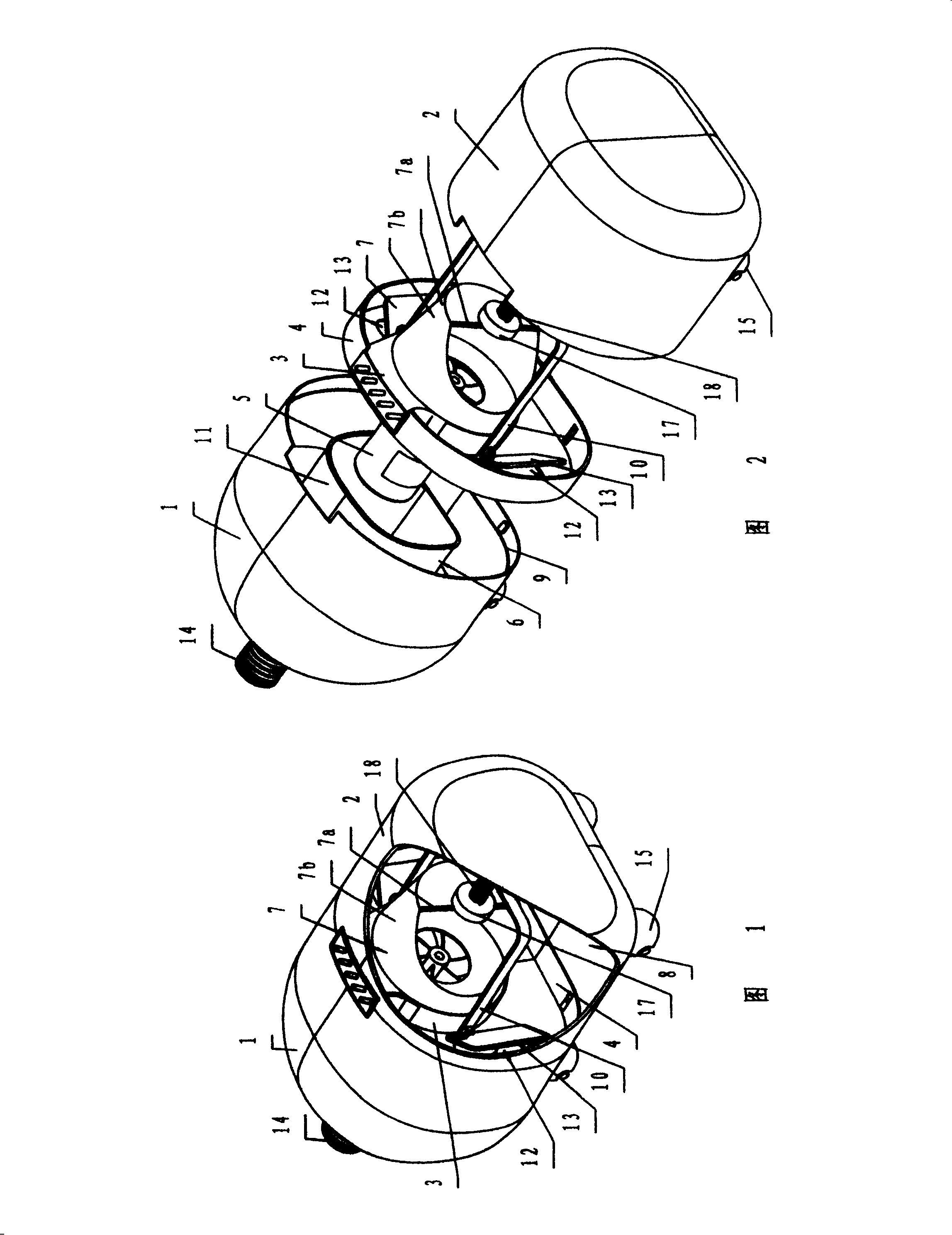
[0015] Referring to Fig. 1 or Fig. 2, this embodiment is a horizontal structure main body.
[0016] Referring to Figure 1 or Figure 2, the body 1 and the card cover 2 constituting the main body are respectively provided with positioning steps 9, the body 1 and the card cover 2 are respectively fitted from the two ends of the support seat 4, and the support seat 4 is clamped between them . The space in the housing is divided into two laterally by the support base 4 , where the motor 5 is located at one end is the air intake passage 6 , and the filter 7 is located at the end where the dust collection chamber 8 is located. With such a design, the gas entering the dust collecting chamber 8 first rotates in the dust collecting chamber 8 and then passes through the filter 7. Certainly, some heavy dust will be separated and settled before reaching the filter 7, thereby reducing the load on the filter 7. .
[0017] Referring to Fig. 1 or Fig. 2, the filter 7 is a bag filter, which i...
example 2
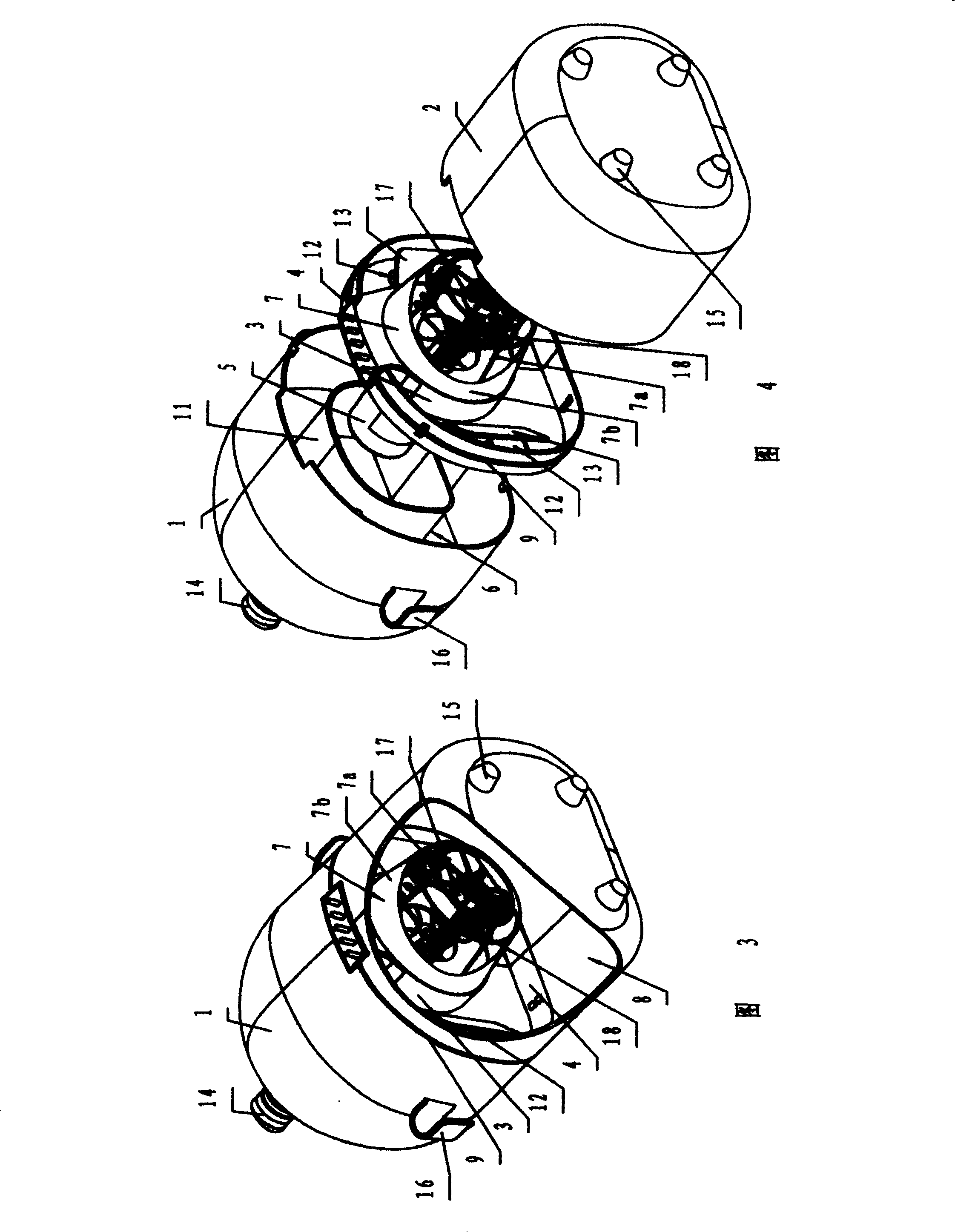
[0023] Referring to Fig. 3 or Fig. 4, this embodiment is a portable structural main body that can be used on the back.
[0024] Referring to Fig. 3 or Fig. 4, the fan 3 is installed on a disc-shaped supporting base 4, and the surface of the supporting base 4 is provided with an annular positioning boss 9, and the body 1 and the card cover 2 constituting the main body are respectively fitted from both ends, and the supporting base 4 is sandwiched between the two.
[0025] Referring to Fig. 3 or Fig. 4, filter 7 is to put cloth bag 7b on the outer surface of a coronal fence cover 7a and form, and its sack is also clamped and fixed on the inlet of blower fan 3 equally. One end of three compression springs 18 is against the crown-shaped fence-like frame 7a, and the other end is against the edge of the fan inlet to stretch the filter bag; the vibrator 17 is fixed at the bottom center of the crown-shaped fence-like frame 7a.
[0026] Referring to FIG. 3 or FIG. 4 , the two sides of...
PUM
 Abstract
Description
Claims
Application Information
 - R&D
- Intellectual Property
- Life Sciences
- Materials
- Tech Scout
- Unparalleled Data Quality
- Higher Quality Content
- 60% Fewer Hallucinations
Browse by: Latest US Patents, China's latest patents, Technical Efficacy Thesaurus, Application Domain, Technology Topic, Popular Technical Reports.
© 2025 PatSnap. All rights reserved.Legal|Privacy policy|Modern Slavery Act Transparency Statement|Sitemap|About US| Contact US: help@patsnap.com


