Fixing device

A fixing device and mounting hole technology, applied in the direction of thin plate connection, connecting member, rivet, etc., can solve the problems of looseness, reduced operability, and heavy burden on the operator, and achieve the effect of reducing burden, good operability, and achieving stability

Inactive Publication Date: 2008-08-13
NIFCO INC
View PDF8 Cites 1 Cited by
  • Summary
  • Abstract
  • Description
  • Claims
  • Application Information

AI Technical Summary

Problems solved by technology

[0008] However, the insertion force when inserting the pin into the grommet with and without the formed ceiling is large, and if the insertion force is too large, the burden on the operator is also large, causing the Reduced operability
On the other hand, if the insertion force is set based on the case with a molded ceiling, looseness will occur without a molded ceiling

Method used


Image

  • Fixing device
  • Fixing device
  • Fixing device

Examples


Embodiment Construction

[0035]Hereinafter, a fixing device according to an embodiment of the present invention will be described with reference to the accompanying drawings.

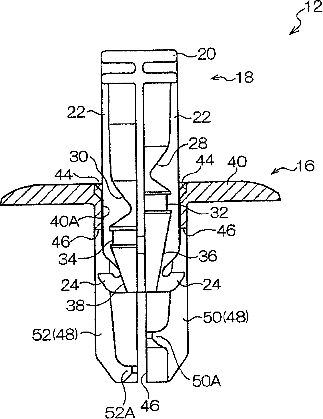
[0036] Such as Figure 4 (A), Figure 4 As shown in (B), the roof panel 14 is installed on the roof panel 10 by the fixing device 12 (in addition, in Figure 4 (A) shows the case where there is a formed ceiling 54 as a cushioning member between the roof panel 10 and the ceiling panel 14. Figure 4 (B) shows the case without the shaped ceiling 54). The case where the roof panel 10 and the roof panel 14 have the formed roof 54 will be described below.

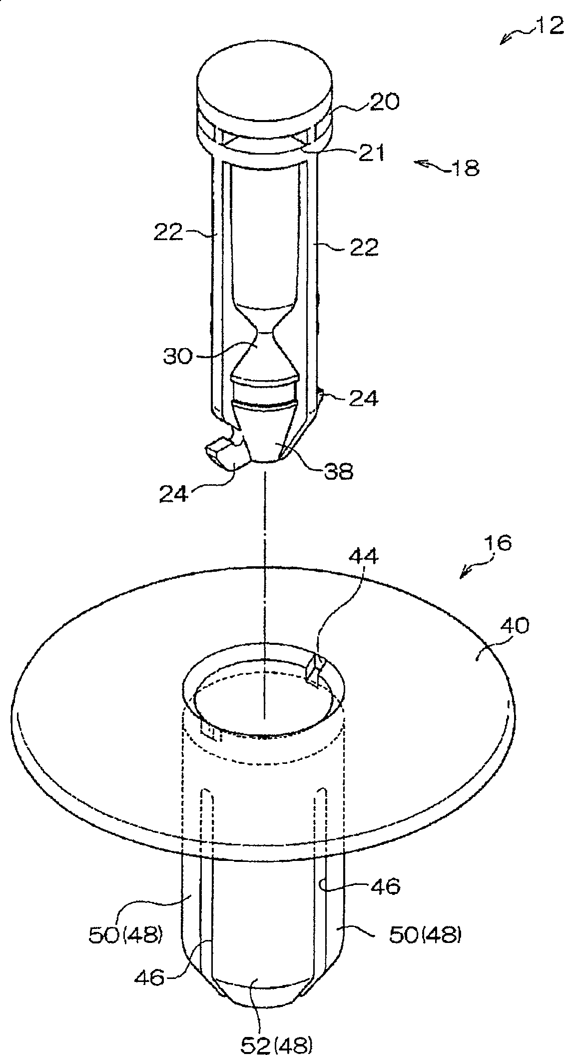
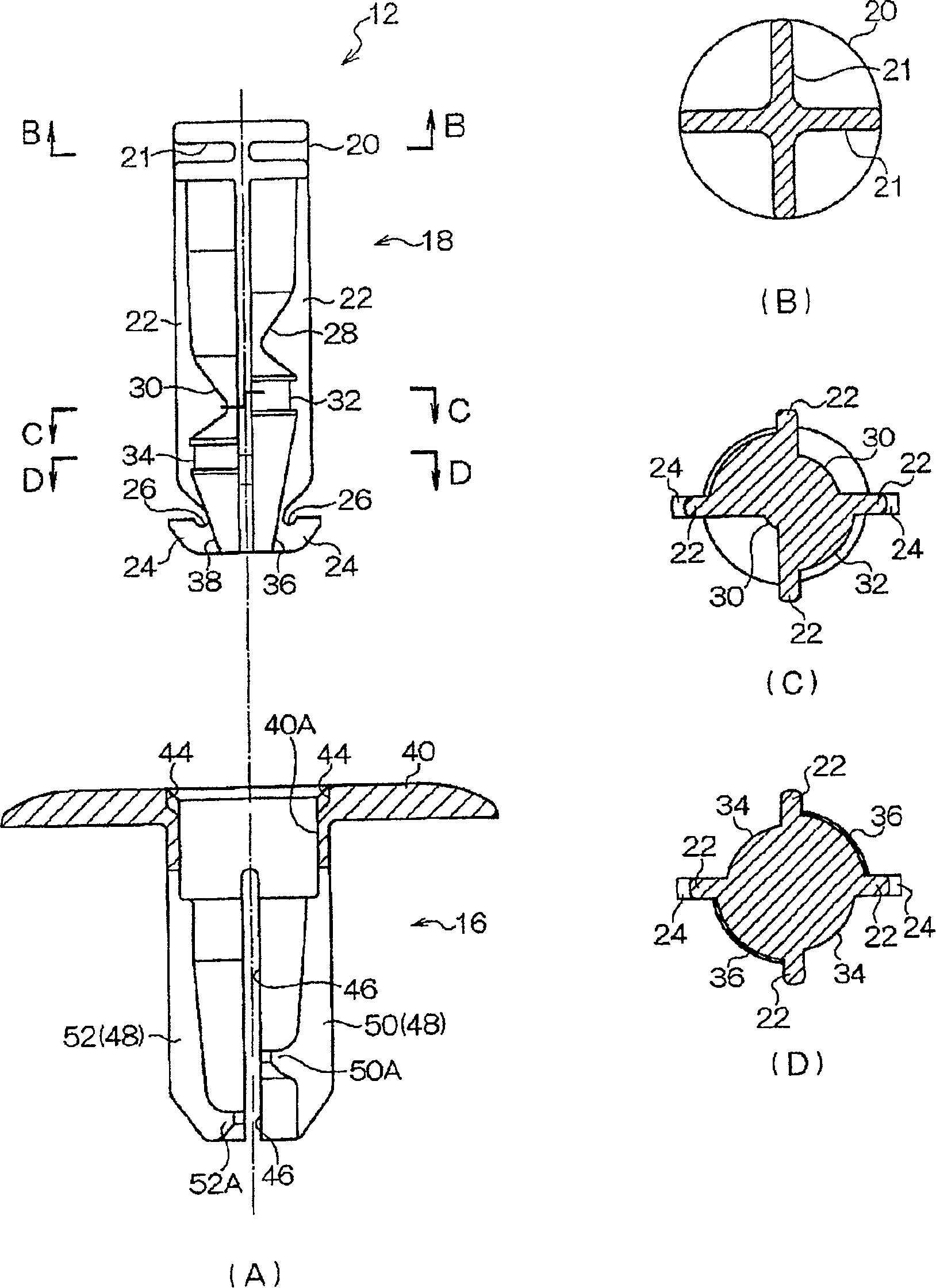
[0037] The fixing device 12 is composed of a cylindrical grommet 16 that can be inserted through the mounting holes 10A, 54A, and 14A respectively formed on the roof panel 10, the formed ceiling 54, and the ceiling panel 14, and a pin that can be inserted into the grommet 16. 18 poses.

[0038] Such as figure 1 and figure 2 As shown in (A), the pin 18 has a substantially c...


PUM


Abstract

The present invention provides a fastener not rattling even when the plate thickness of a plate material is small, and providing excellent workability even when the plate thickness of the plate material is large. Positions of recessed parts 32 and 34 formed in a pin 18 are changed in the axial direction of the pin 18, and arranged alternately at intervals of 90 degree in the circumferential direction of the pin 18. Also, positions of projections 50A and 52A formed on leg pieces 50 and 52 of a grommet 16 are changed in the axial direction of a leg 48 so that projections can be locked to the recessed parts 32 and 34 so as to change the spread amount of the leg pieces 50 and 52 in order to extend outward the leg piece 50 more than the leg piece 52. Accordingly, since the plate material 56 can be held between at least a flange 40 and the leg piece 50 when a molded ceiling 54 is absent, the fastener 12 does not rattle. On the other hand, when the molded ceiling 54 is present, though the insertion resistance on the leg piece 50 side is large, the insert force for the pin 18 is reduced smaller than that in a case that the plate material 56 is held by the leg piece 50 and the leg piece 52 at the same spread angle since the insertion resistance for the leg piece 52 side is small. Accordingly, workability can be improved by setting the insertion force to a proper one not applying an undue load on a worker.

Description

technical field [0001] The present invention relates to a fixing device used when attaching a roof panel to a roof panel of a vehicle roof surface or the like. Background technique [0002] Conventionally, a ceiling panel attached to a roof panel of the vehicle ceiling surface is provided on the ceiling surface of the vehicle interior. In this way, the roof panel can be mounted to the roof panel with a fastening arrangement consisting of pins and grommets. [0003] For example, when attaching a ceiling panel using the fixing device of Patent Document 1 (JP-A-11-27052), first, a pin is inserted into a cylindrical grommet so that the pin cannot be pulled out from the grommet. Next, insert the four legs of the grommet into the respective mounting holes formed on the roof panel and ceiling panel, and press the pins into the depth of the grommet. [0004] Here, a deployment point smaller than the outer diameter of the pin is provided on the inner surface of the opposite leg, an...

Claims


Application Information

Patent Timeline
Patent Type & Authority Patents(China)
IPC IPC(8): F16B19/10F16B5/00
Inventor 矶村恒久
Owner NIFCO INC
Why Eureka
Try Eureka