
Rapid response electric heat exchanger
A heat exchanger and electric energy technology, applied in the field of fluid fluid heat exchangers and fluid heat exchangers, can solve the problems of not easy to manufacture, the Rezabek system does not have a compact structure, etc.
- Summary
- Abstract
- Description
- Claims
- Application Information
AI Technical Summary
Problems solved by technology
Method used
Image

Examples
Embodiment Construction
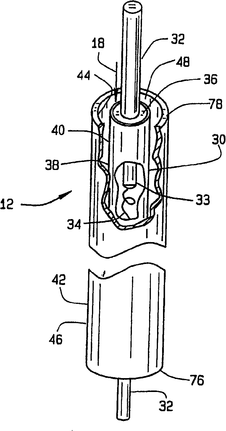
[0036] Referring to the drawings, a preferred embodiment of the fluid heating system of the present invention is shown in FIG. 4 and generally designated 10 . The fluid heating system 10 includes a housing 13 containing a body 17 defining an elongated upper portion 25 and a lower portion 26 having a fluid heat exchanger 12 disposed therein providing means for heating a fluid 18 to a predetermined temperature. heating equipment. Fluid 18 enters upper section 25 from return side 22 of fluid heating system 10 and is heated while flowing along upper section 25 and lower section 26 . The heated fluid 18 then exits the lower portion 26 and flows into the inlet side 24 and through the remainder of the fluid heating system 10 . Once circulated, the fluid 18 flows through the return side 22 so that the above process is repeated. The temperature level of the fluid 18 is maintained by a temperature control system 20 .
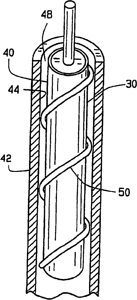
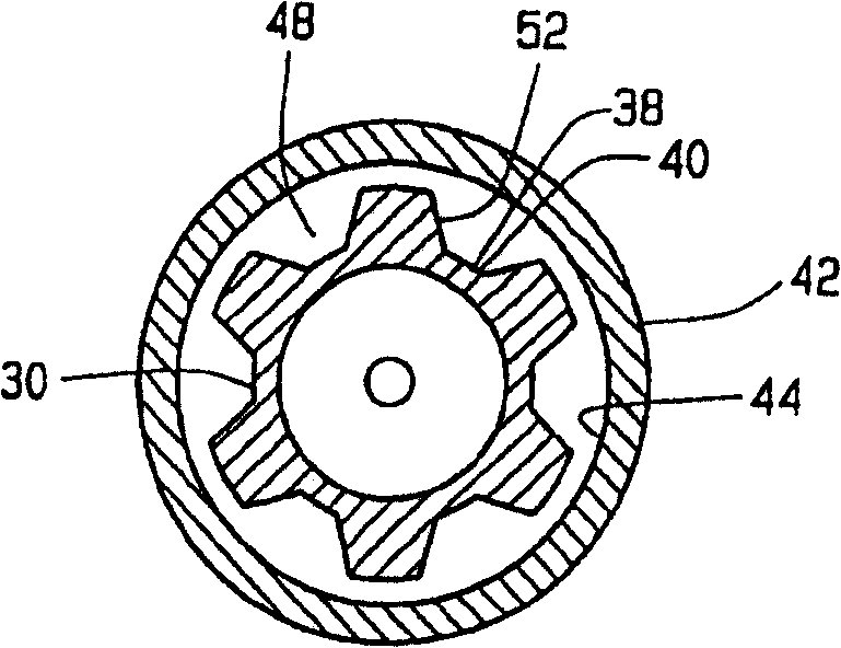
[0037] refer to figure 1 and 4, the fluid heat exchanger 12 incl...
PUM
 Abstract
Description
Claims
Application Information