Speed regulator

A technology of speed adjustment and constant speed, applied in the direction of vehicle gearboxes, machines/engines, transmissions, etc., can solve the problems of increased weight, dust and wear, and achieve the effects of cost saving, low wear and novel layout

Inactive Publication Date: 2014-04-23
卡勒·坦斯卡伦
View PDF3 Cites 0 Cited by
  • Summary
  • Abstract
  • Description
  • Claims
  • Application Information

AI Technical Summary

Problems solved by technology

On the other hand, a front and rear derailleur combination requires gears at the front and rear, as well as shift levers at both gear ends, which adds weight
Current transmission components are prone to failure due to dirt and wear

Method used


Image

  • Speed regulator
  • Speed regulator
  • Speed regulator

Examples


Embodiment Construction

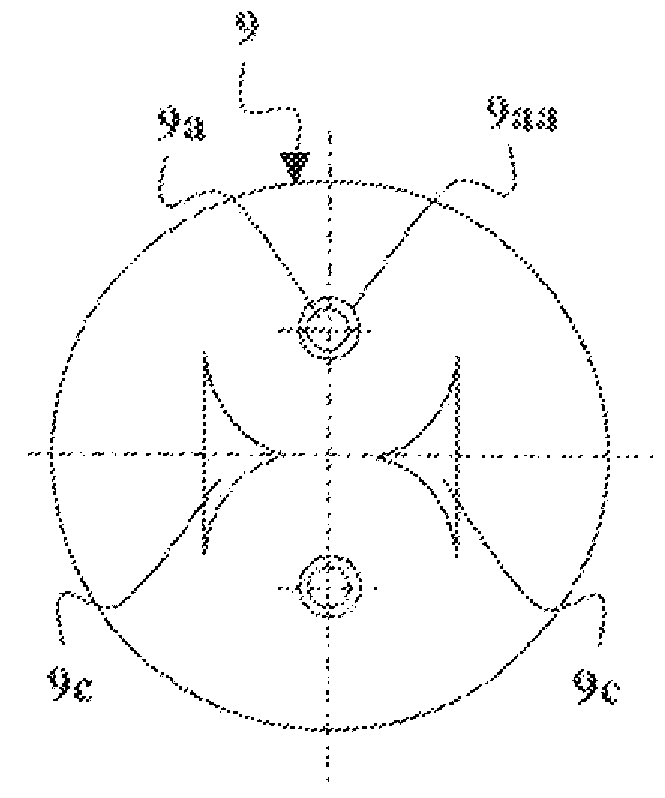
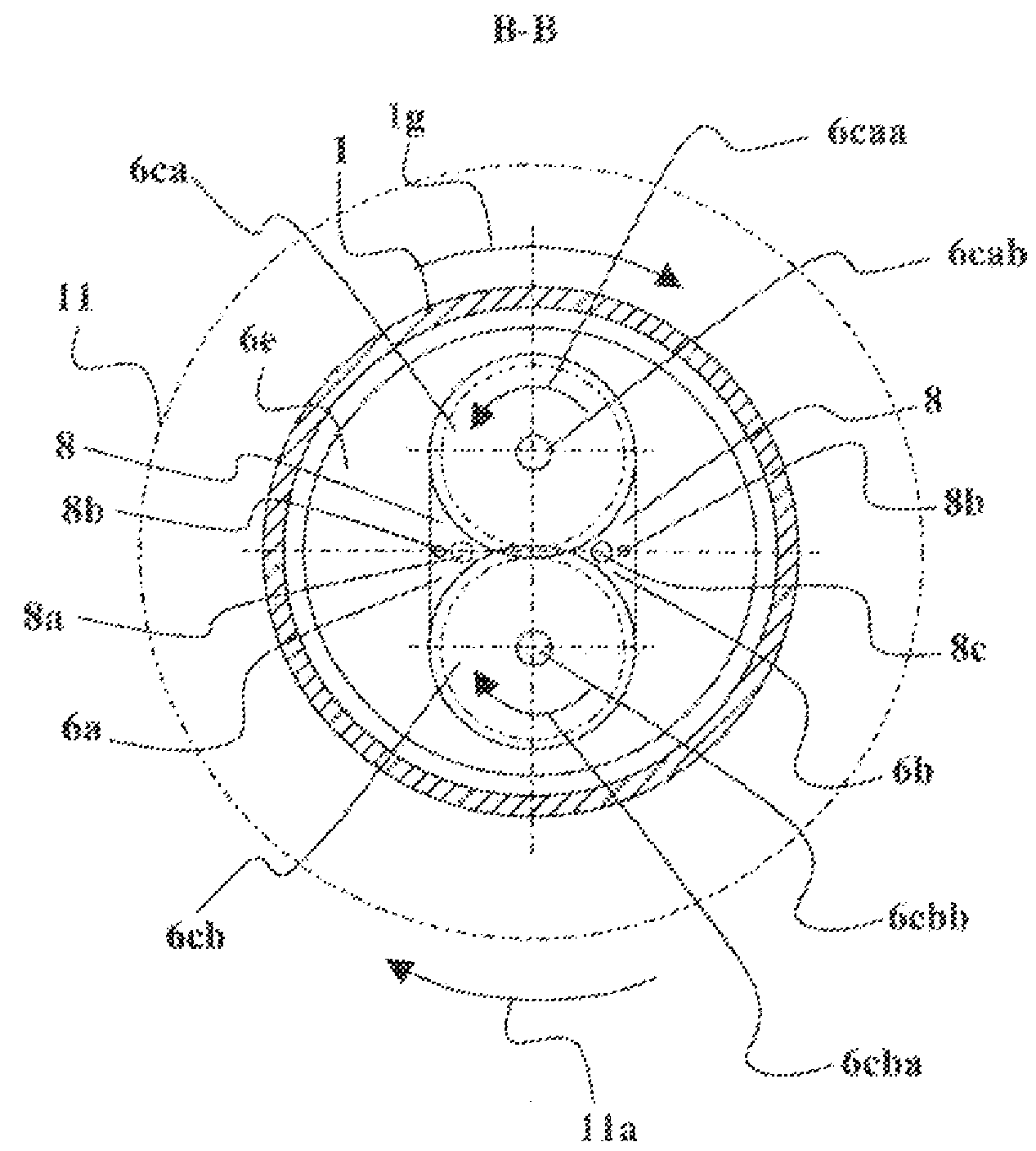
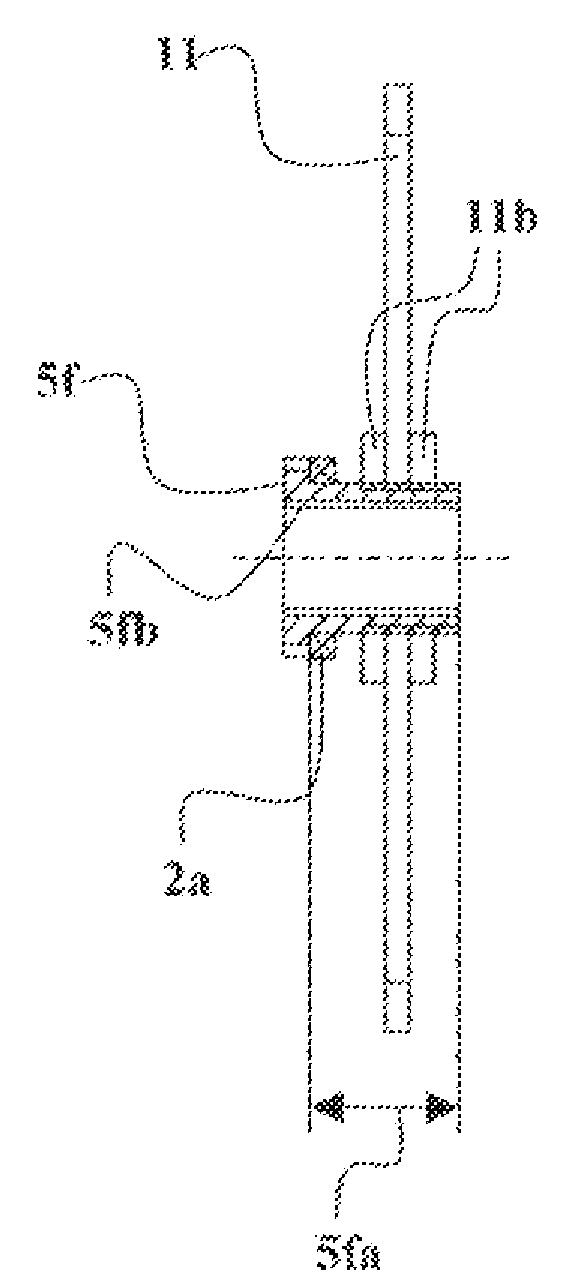
[0047]The figure shows the following components and items of the speed regulator: body 1 with outer surface 1a, inner surface 1b, collar 1c, shoulder 1d, internal thread 1f and rotation direction arrow lg of body 1. The outer surface 1a includes a rotating part laa, and the bicycle chainstay includes a mounted part lab. There is a drive end 2, in which there is a bearing 2a. There are ends 3. There is a shaft 4 in which there are a support shaft 4a, a mounting nut 4b, a collar 4c, a main bearing 4d and a hole 4e. The support shaft 4a includes threads 4aa for mounting nuts 4b. The collar 4c includes a mounting hole 4ca in which the seal 4caa is in a groove. There is a drive end shaft 5 in which there are a support shaft 5a, a mounting nut 5b, a collar 5c, a main bearing 5d, a hole 5 and a rotating gear 5f. The support shaft 5a includes threads 5aa for mounting nuts 5b. The collar 5c includes a bore 5ca and a pump shaft bearing 5cb. The rotary gear 5f includes a sleeve 5fa...


PUM


Abstract

The invention relates to a speed regulator of a bicycle, which speed regulator is in the rear hub or the pedal centre of the bicycle, which includes one or more hydraulic pumps (6) which is rotated by a rear pinion (11) or by the pedals, which hydraulic pump (6) rotates one or more hydraulic motors (7), which hydraulic motor / hydraulic motors (7) rotates / rotate the rear wheel of the bicycle. According to the invention, the rotation speed of the hydraulic pump (6) can be steplessly changed when the rear pinion 11 or the pedals rotate at constant speed.

Description

technical field [0001] The invention relates to a speed regulator according to the preamble of claim 1 attached hereto. Background technique [0002] At present, the transmission of bicycles has been implemented as a so-called hub gear transmission, or by a combination of front and rear derailleurs. [0003] In hub gearing, the transmission is built into the rear hub by using various gear structures. Then, the number of gears is usually 2-7. [0004] In a front-rear derailleur combination, the bicycle includes a separate front derailleur positioned in connection with the pedals, and a rear derailleur in the rear hub. Then the front detachment uses 1-3 gears, and the number of gears at the rear detachment is usually 6-10. This provides up to 30 speeds whose gear ratios can, and usually will, overlap. The job of the front and rear shifters is to shift the chain from one gear to the other. [0005] The main problem with the currently known transmissions is that the number ...

Claims


Application Information

Patent Timeline
Patent Type & Authority Applications(China)
IPC IPC(8): B62M19/00F16H39/06F04C14/18
CPCF15B7/005F04C2/344F04C14/08F04C14/185F16H39/06B62M19/00F03C2/08F04C2/10F04C11/003
Inventor 卡勒·坦斯卡伦
Owner 卡勒·坦斯卡伦
Why Eureka
Try Eureka