
Regulating mechanism for electronic viewfinder

An electronic viewfinder and adjustment mechanism technology, which is applied to viewfinders, cameras, optics, etc., can solve the problems of easy deformation of guide rods, obstacles to the rotation of driving wheels, breakage, etc., to achieve diopter adjustment, fewer components, and easy assembly. Effect

Inactive Publication Date: 2008-10-15
ASIA OPTICAL CO INC
View PDF4 Cites 0 Cited by
  • Summary
  • Abstract
  • Description
  • Claims
  • Application Information

AI Technical Summary

Problems solved by technology

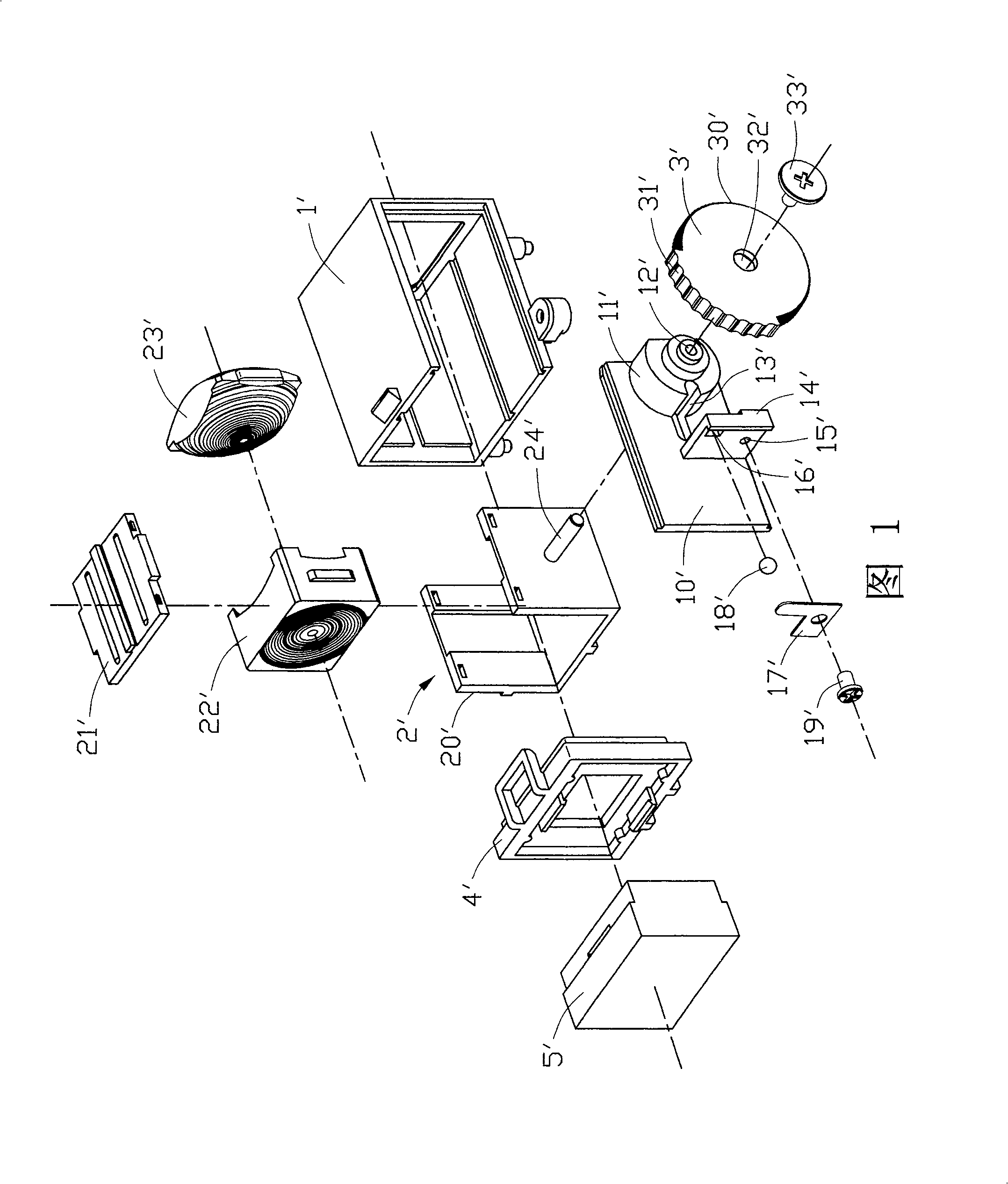
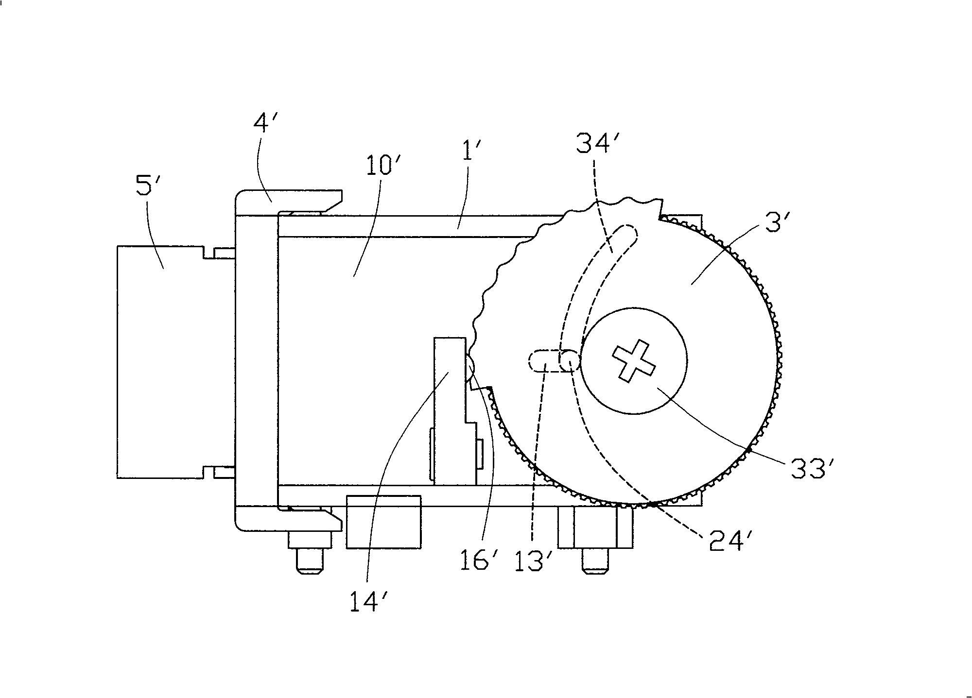
[0005] However, the above-mentioned prior art scheme that adopts the driving wheel with a sliding track to cooperate with the guide rod has a relatively small diameter and a long length of the guide rod, that is, the ratio of its diameter to length is small, so the guide rod is used It is easy to be deformed or even broken, which directly affects the drive and adjustment of the mirror chamber inside the viewfinder
Moreover, the cooperation between the guide rod and the sliding track of the driving wheel needs to accurately calculate the curvature of the sliding track and control its smoothness during manufacture, otherwise it is difficult to achieve the effect of driving the mirror chamber at a constant speed and accurately, and cause the shaking of the mirror chamber when moving This phenomenon affects the projection resolution of the viewfinder, and in severe cases, the rotation of the driving wheel may be hindered due to poor coordination between the guide rod and the sliding track, making it impossible to adjust the diopter of the viewfinder

Method used


Image

  • Regulating mechanism for electronic viewfinder
  • Regulating mechanism for electronic viewfinder
  • Regulating mechanism for electronic viewfinder

Examples


Embodiment Construction

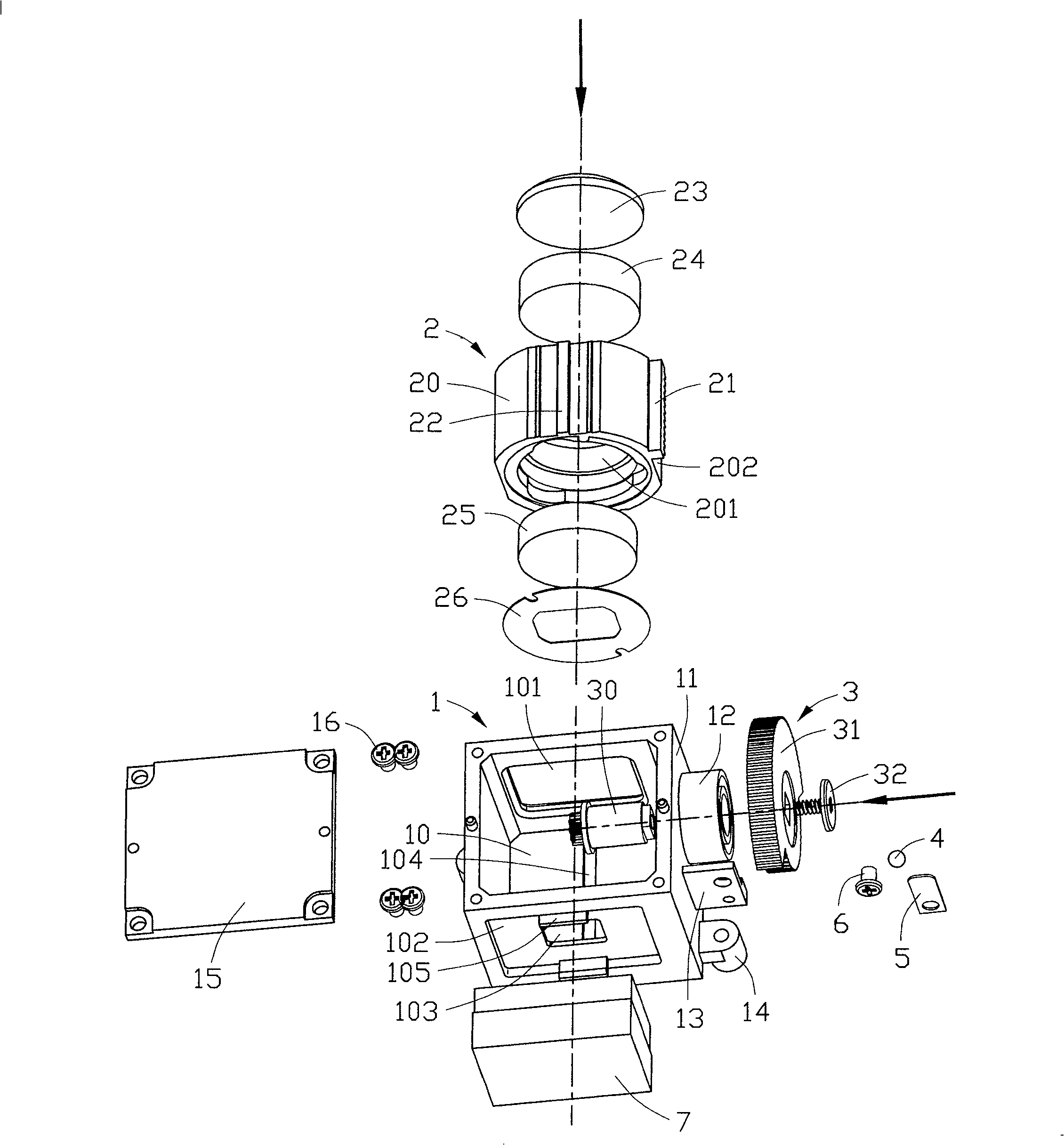
[0024] see image 3 The adjustment mechanism of the electronic viewfinder shown includes a main body 1, a mirror chamber 2, a driving wheel 3, steel balls 4, shrapnel 5, screws 6 and other components, wherein the main body 1 is a square frame with a The storage space 10 of the storage mirror room 2 . Please refer to Figure 4 The front end wall and the rear end wall of the main body 1 are provided with see-through holes 101, 103 respectively for users to observe the images displayed on the liquid crystal display 7, and a recessed slot 102 is provided outside the rear end wall of the main body 1 to The liquid crystal display 7 is used for installation, and a hook 105 is provided at the upper and lower edges of the embedding groove 102 to fix the liquid crystal display 7 . A guide groove 104 extending along the front and rear directions is defined on the bottom wall of the receiving space 10 of the main body 1 . In addition, a cylindrical wheel base 12 protrudes from the oute...


PUM


Abstract

The present invention discloses a regulating mechanism for electronic viewfinder, it is applicable to digital camera on video camera. The invented regulating mechanism includes frame self-body, lens chamber placed in said self-body interior and drive wheel mounted on said self-body in the turnable connection mode. On said lens chamber a rack and a guide rib are set, in the self-body is set a guide groove which can be matched with said guide rib, on the drive wheel is correspondently set a gear which can be matched with the rack of lens chamber. When the drive wheel is turned, the gear is meshed with the rack, so that the circumferential motion of the drive wheel can be converted into straight line motion of rack so as to drive lens chamber and make it be moved along guide groove, and can attain the effect of uniformly, stably and accurately regulating electronic viewfinder.

Description

【Technical field】 [0001] The invention relates to an adjustment mechanism of an electronic viewfinder, in particular to a mechanism suitable for digital cameras or video cameras, which has a diopter adjustment function and can properly compensate some degrees of myopia, so that the operator can see clearly and accurately from the viewfinder. The adjustment mechanism of the electronic viewfinder of the screen. 【Background technique】 [0002] Viewfinders currently used in digital cameras mainly include SLR (Single Lens Reflex) viewfinders, liquid crystal viewfinders and electronic viewfinders (EVF, Electronic Viewfinder). Among them, SLR viewfinders are most in line with the habits of traditional photographers. Most accurate, but most digital SLR cameras are too expensive for ordinary non-professional photographers to afford. Although the LCD viewfinder has many advantages, its defects are also very obvious. For example, enabling the LCD display viewfinder is a very power-con...

Claims


Application Information

Patent Timeline
Patent Type & Authority Patents(China)
IPC IPC(8): G03B13/10G03B13/02
Inventor 邓起兵
Owner ASIA OPTICAL CO INC
Learn More