Rotary adjuster
A regulator, rotary technology, applied in the direction of liquid shock absorber, can solve the problems of difficult to set valve core, increase the installation space of rotary regulator, etc., to achieve the effect of expanding the scope and improving the pass rate
- Summary
- Abstract
- Description
- Claims
- Application Information
AI Technical Summary
Problems solved by technology
Method used
Image
Examples
Embodiment 1
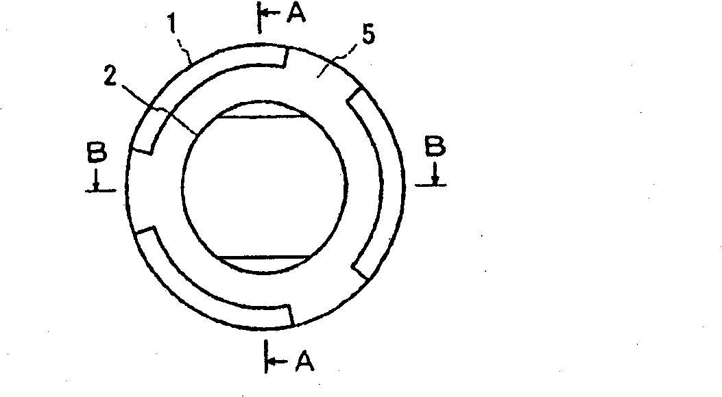
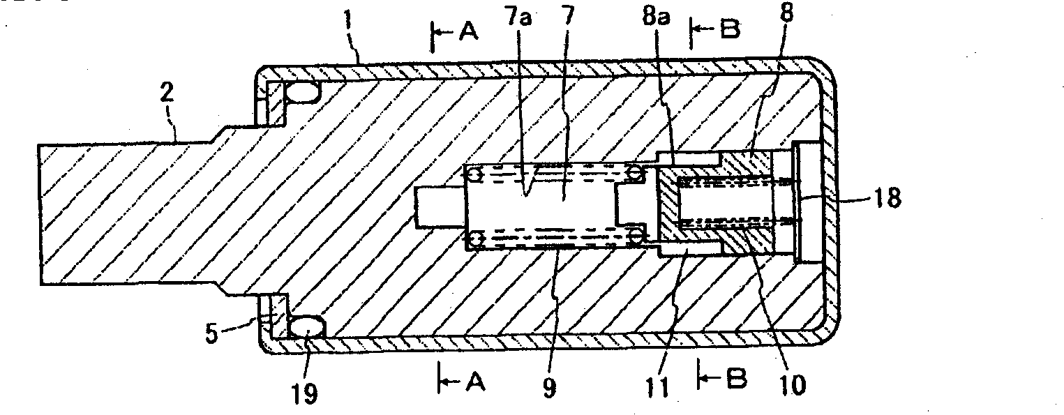
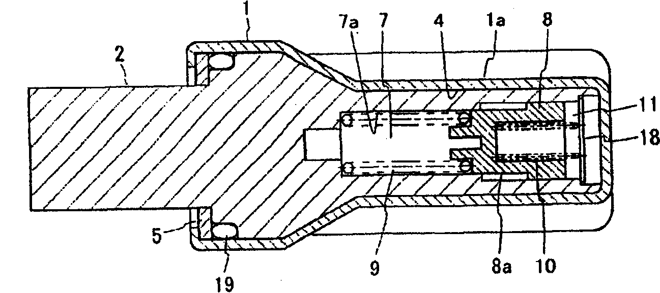
[0086] figure 1 - Fig. 7 is a diagram showing a rotary regulator of Embodiment 1 of the present invention. As shown in these figures, the rotary regulator of this embodiment has a housing 1, a shaft 2, a vane 3, a partition 4, and a valve mechanism.
[0087] The shell 1 is hollow, with one end open and the other end closed. The opening of the case 1 is closed by a cover 5 . The cover 5 is installed by caulking the end of the housing 1 . The housing 1 has a partition wall 4 that partitions a space formed between the housing 1 and the shaft 2 . The housing 1 and the partition wall 4 are integrally formed by press working. In this way, the recessed portion 1a is formed in the partition wall forming portion, and the recessed portion 1a functions as a joint portion (refer to image 3 ~ Figure 5). Viscous fluid such as silicone oil is filled in the casing 1 .
[0088] The shaft 2 is arranged rotatably relative to the housing 1 in the housing 1 . Blades 3 integrally formed w...
Embodiment 2
[0106] The shape of the spool 8 of the rotary regulator of this embodiment is different from that of the rotary regulator of the first embodiment. That is, the spool 8 of the present embodiment is as shown in Figure 14 and Figure 15 As shown, it has a tapered surface 8b on its outer periphery.
[0107] Figure 14 shows the state before the spool 8 advances in the working chamber 7, Figure 15 The state after the spool 8 moves forward in the working chamber 7 is shown. As shown in these figures, according to the valve mechanism having the spool 8, as the movement distance of the spool 8 that moves forward in the working chamber 7 increases, the wall surface formed on the peripheral wall 7a of the working chamber 7 and the spool 8 The area of the flow path 14 between the tapered surfaces 8b is reduced, thereby increasing the throttling amount. Therefore, the same effect as that of the first embodiment can be obtained in this embodiment as well.
Embodiment 3
[0109] The shape of the spool 8 of the rotary regulator of this embodiment is different from that of the rotary regulator of the first embodiment. That is, the spool 8 of the present embodiment is as Figure 16 As shown, it has a substantially V-shaped groove 8c on its outer periphery.
[0110] According to the valve mechanism having the spool 8, as the movement distance of the spool 8 moving forward in the working chamber 7 increases, the flow path formed between the wall surface of the peripheral wall 7a of the working chamber 7 and the groove 8c of the spool 8 The area of 14 is reduced, thereby can increase throttling amount. Therefore, the same effect as that of the first embodiment can be obtained in this embodiment as well.
PUM
 Abstract
Description
Claims
Application Information
 - R&D
- Intellectual Property
- Life Sciences
- Materials
- Tech Scout
- Unparalleled Data Quality
- Higher Quality Content
- 60% Fewer Hallucinations
Browse by: Latest US Patents, China's latest patents, Technical Efficacy Thesaurus, Application Domain, Technology Topic, Popular Technical Reports.
© 2025 PatSnap. All rights reserved.Legal|Privacy policy|Modern Slavery Act Transparency Statement|Sitemap|About US| Contact US: help@patsnap.com


