A new energy vehicle braking device

A new energy vehicle and brake device technology, applied in the direction of brake parts, drum brakes, brake types, etc., can solve the problems of inability to self-buffer and protect, and achieve the effect of good buffer protection

Active Publication Date: 2022-07-15
CHONGQING WANGCHENG TECH
View PDF0 Cites 0 Cited by
  • Summary
  • Abstract
  • Description
  • Claims
  • Application Information

AI Technical Summary

Problems solved by technology

[0004] The purpose of the present invention is to provide a new energy vehicle braking device to solve the problem that the new energy vehicle braking device cannot self-buffer and protect when it receives a large reaction force

Method used


Image

  • A new energy vehicle braking device
  • A new energy vehicle braking device
  • A new energy vehicle braking device

Examples


Embodiment

[0083] In order to make the technical means, creation features, achievement goals and effects realized by the present invention easy to understand, the present invention will be further described below with reference to the drawings and specific embodiments.

[0084] combine Figure 1 to Figure 13 The high pressure resistant punching jig of the present invention will be described in detail.

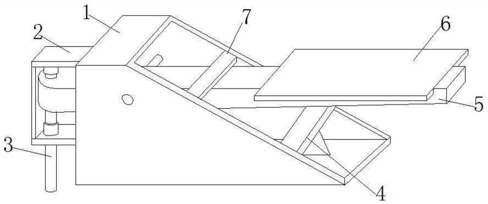
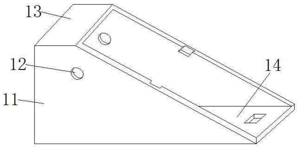
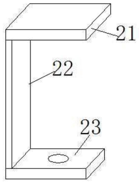
[0085] The braking device for a new energy vehicle in this embodiment includes a frame 1 . The braking device of the new energy vehicle further includes a fixing frame 2 , and the fixing frame 2 is fixed on the outer wall of the frame 1 with bolts. The pressing plate 5 is pivotally connected to the frame 1 . The transmission member 3 is arranged in the fixed frame 2 ; the transmission member 3 is hinged to one end of the pressing plate 5 extending into the interior of the fixed frame 2 . The auxiliary support frame 4 is fixed to the bottom of the inner cavity of the frame 1 with bolts....


PUM


Abstract

The invention discloses a braking device for a new energy vehicle, comprising a frame and a fixing frame. The fixing frame is fixed on the outer wall of the frame; the pressing plate is pivotally connected in the frame; the transmission part is arranged in the fixing frame; The auxiliary support frame is fixed at the bottom of the inner cavity of the frame; the positioning member is pivotally connected to the upper edge of the frame and is slidably matched with the pressing plate; the friction member is fixed on the upper side of the other end of the pressing plate; It includes a first adjustment seat, the first adjustment seat is fixed on the upper end of the pull rod; the second adjustment seat is fixed in the middle of the pull rod; the friction piece includes an installation frame, and also includes a second side plate, and the second side plate is fixed on the lower side of the installation frame The first screw is screwed into the second side plate; a plurality of first screws are arranged along the length of the second side plate; the bearing plate is fixed at the bottom of the inner cavity of the mounting frame; the friction block is fixed on the bearing plate The upper side of the plate; the adjustment block is fixed between two adjacent friction blocks.

Description

technical field [0001] The invention relates to the technical field of automobile braking, in particular to a new energy automobile braking device. Background technique [0002] During the braking process of the car, the car braking device directly applies force to the wheels for braking, and this process generates a reaction force to the car braking device. When emergency braking occurs, the braking force generated in a short period of time is large. , it will cause great damage to the brake parts themselves, and even lead to the breakage of the brake parts of the automobile. However, the direct hard contact between the existing brake components and the wheel makes it difficult to avoid the direct hard force, and the existing brake components lack necessary buffer components and cannot buffer the forces acting on them. Its own protection capabilities are limited. [0003] Therefore, it is necessary to provide a braking device for a new energy vehicle. When a reaction forc...

Claims


Application Information

Patent Timeline
Patent Type & Authority Patents(China)
IPC IPC(8): F16D49/00F16D65/06F16D69/00
CPCF16D49/00F16D65/0006F16D65/06F16D69/00
Inventor 吕瑶
Owner CHONGQING WANGCHENG TECH
Why Eureka
Try Eureka