Fiber dyeing device for spinning

A dyeing device and fiber technology, which is applied in the processing of textile materials, equipment configuration for processing textile materials, textiles and papermaking, etc., can solve problems such as processing, affecting production efficiency, and disadvantages.

Inactive Publication Date: 2021-02-12
颜广梅
View PDF0 Cites 0 Cited by
  • Summary
  • Abstract
  • Description
  • Claims
  • Application Information

AI Technical Summary

Problems solved by technology

[0002] The textile industry is inseparable from the processing of the dyeing process. The existing dyeing process includes two methods: spraying and dip-dyeing. The spraying method is suitable for surface dyeing, and the dip-dyeing is suita

Method used


Image

  • Fiber dyeing device for spinning
  • Fiber dyeing device for spinning
  • Fiber dyeing device for spinning

Examples


Embodiment 1

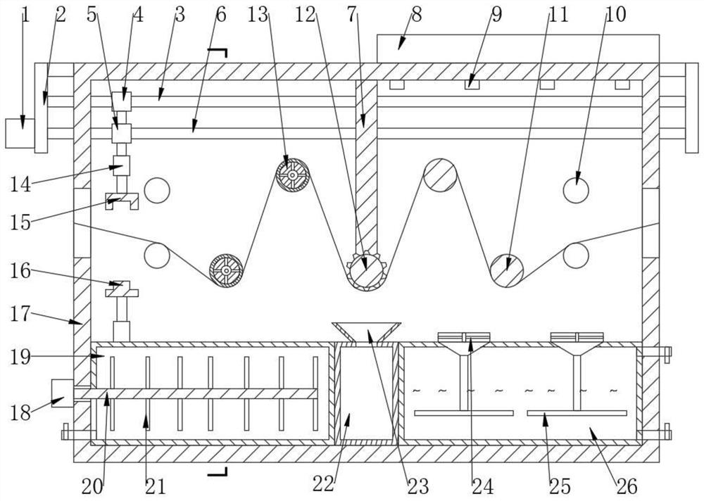
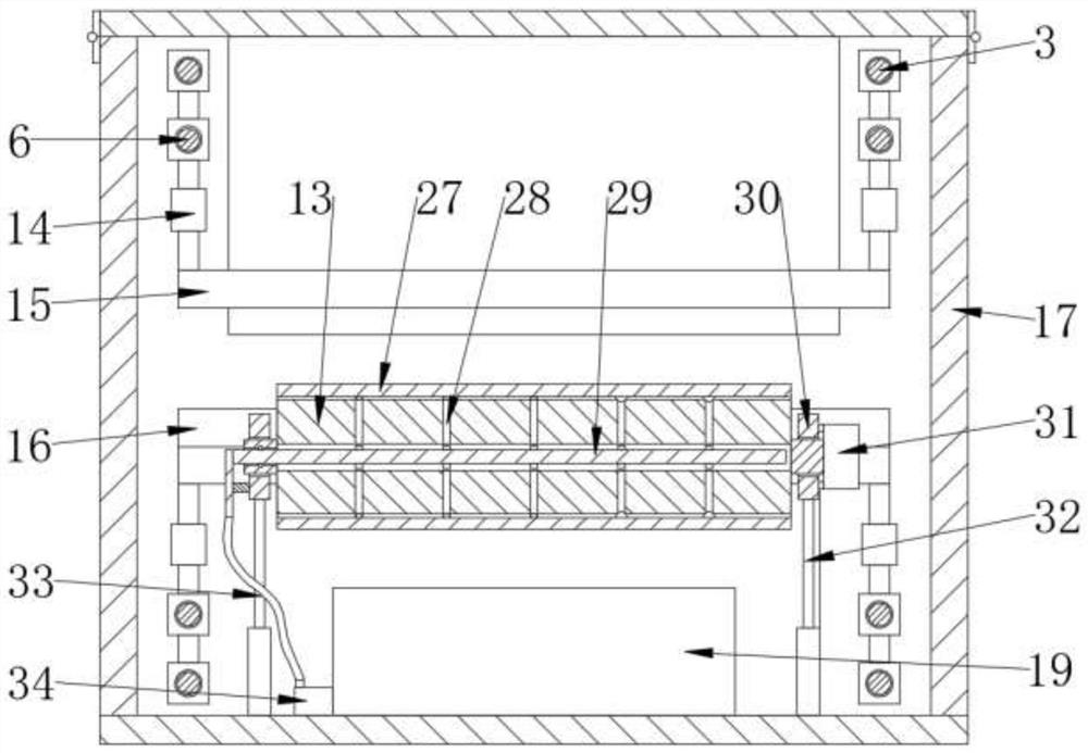
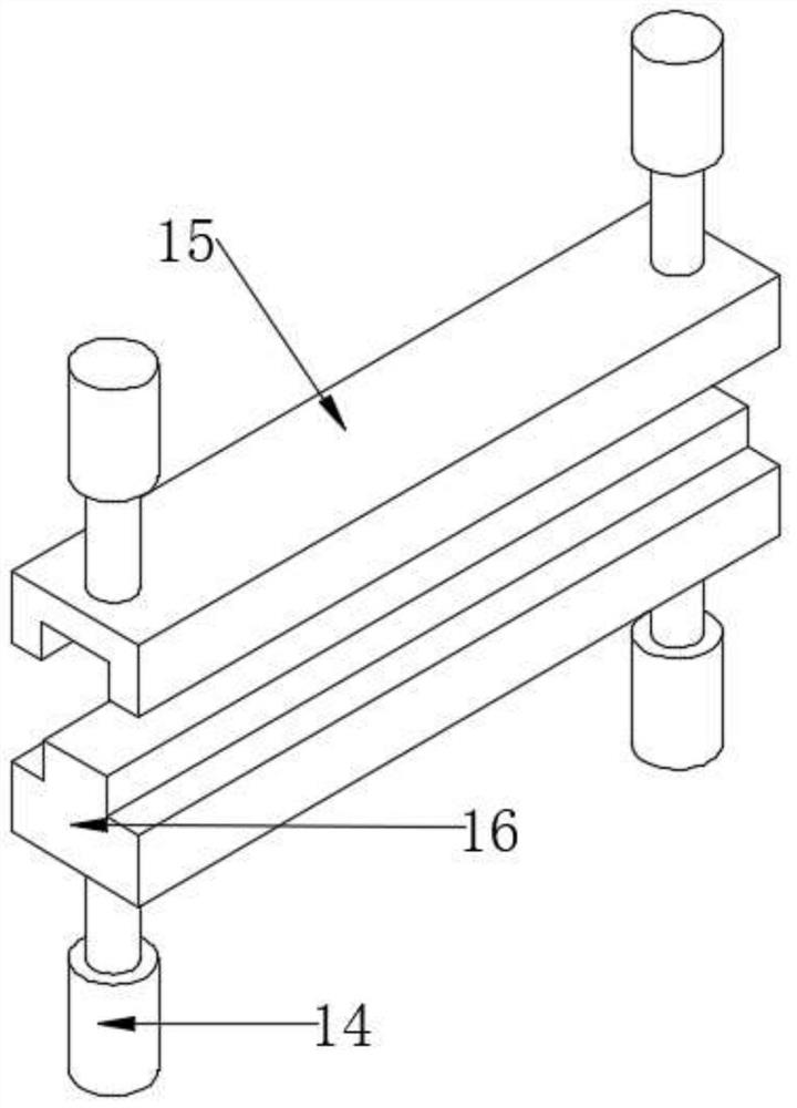
[0023] see Figure 1-4 , the present embodiment provides a fiber dyeing device for weaving, which includes an outer casing 17, and two ends of the outer casing 17 are provided with horizontal "I"-shaped gaps as inlet and outlet ports. Both ends of the outer casing 17 are provided with guide wheels 10, and are also provided with a traction mechanism. The traction mechanism includes an upper clamping part 15, a lower clamping part 16 and a driving structure. There is a groove, the lower clamping part 16 is provided with a protrusion corresponding to the shape of the groove, the driving structure includes a driving motor 1, a threaded collar 5 and a driving screw 6, and the outer casing 17 is fixedly arranged There is a supporting frame 2 for supporting, the driving motor 1 is fixedly arranged on the supporting frame 2 and connected to the driving screw 6 by driving, the threaded collar 5 is threaded on the driving screw 6 and its Between the upper clamping part 15 and the lower...

Embodiment 2

[0032]On the basis of Embodiment 1, a stirring mechanism is also provided, and the stirring mechanism includes a stirring motor 18, a transmission shaft 20 and a stirring rod 21, and the stirring motor 18 is fixedly arranged and its driving connection side is provided with some stirring rods 21 The transmission shaft 20 stirs the paint in the paint bin 19 by being provided with a stirring mechanism, so that the paint in the paint is always in a uniformly mixed state to prevent sedimentation; a purification box 26 is arranged below the drying chamber, and the The purification box 26 is provided with a wind-inducing component 24 and an air-dispersing disk 25, and the air containing a large amount of pigment odor is purified by the purification box 26, thereby reducing the harm to the environment. The purification method in the purification box 26 can be selected Existing chemical purification, or activated carbon adsorption.

Embodiment 3

[0034] On the basis of Embodiment 1, the upper clamping part 15 and the lower clamping part 16 are wave-shaped to enhance the stability of clamping the filamentary fiber raw material.


PUM


Abstract

The invention discloses a fiber dyeing device for spinning, and relates to the field of spinning. The fiber dyeing device comprises an outer shell, wherein transverse I-shaped notches are formed in two ends of the outer shell to serve as a feed port and a discharge port, guide wheels are arranged at two ends in the outer shell, a traction mechanism is further arranged, the interior of the outer shell is divided into a dyeing cavity and a drying cavity by a middle partition plate, a heating component used for supplying heat is arranged on the upper side of the outer shell, and a plurality of hot air nozzles in communication with the heating component are arranged in the outer shell. According to the device, a soft cushion coloring layer is arranged to dye filamentous fibrous materials in adip dyeing mode, dyeing is uniform and thorough, and the efficiency is high; the filamentous fibrous materials before and after dyeing are both roller-shaped, which is convenient for previous and subsequent processing; the traction mechanism is arranged, so that the traction effect is achieved at the beginning, and processing is more convenient.

Description

technical field [0001] The invention relates to the technical field of textiles, in particular to a fiber dyeing device for textiles. Background technique [0002] The textile industry is inseparable from the dyeing process. The existing dyeing process includes spraying and dip-dyeing. The spraying method is suitable for surface dyeing, and the dip-dyeing is suitable for all dyeing. However, the existing dip-dyeing method is mostly to put all the raw materials into a container for dip-dyeing , which will lead to raw material lumps and its confusion, which is not conducive to the processing of subsequent processes and affects production efficiency. Therefore, a fiber dyeing device for weaving is now provided. Contents of the invention [0003] The object of the present invention is to provide a fiber dyeing device for weaving, so as to solve the problems raised in the above-mentioned background technology. [0004] To achieve the above object, the present invention provide...

Claims


Application Information

Patent Timeline
IPC IPC(8): D06B3/06D06B15/00D06B23/02D06B23/04D06B23/20D06B23/24
CPCD06B3/06D06B15/00D06B23/026D06B23/04D06B23/205D06B23/24
Inventor 颜广梅
Owner 颜广梅
Why Eureka
Try Eureka