Pneumatic brake device capable of being circularly used

A technology of pneumatic brakes and cylinders, which is used in transportation and packaging, coiling strips, thin material handling, etc., can solve the problems of increased maintenance costs, increased labor of maintenance personnel, easily damaged brake friction blocks, and reduced machine work efficiency. , to avoid damage to the friction block, avoid mechanical wear and save time

Inactive Publication Date: 2020-10-09
鲁丰织染有限公司
View PDF0 Cites 0 Cited by
  • Summary
  • Abstract
  • Description
  • Claims
  • Application Information

AI Technical Summary

Problems solved by technology

[0003] In order to ensure this requirement, the use status of the brake device of the cloth guide roller is very important. There is a problem that the position of the original manual brake is a little far away from the operating table of the roll changing and rewinding device (about 4 meters), and the workers are in the After operating the traction and rewinding device at the operating platform, go to the manual brake to stop the brake. This period of time takes 1 minute. Calculated at a speed of 60 meters, there must be a 60-meter crease, and it is every time the roll is changed. have to produce so many defects
In addition, manual brakes are different depending on the person, and the adjustment is not the same. It is easy to damage the friction block of the brake, which will greatly increase the maintenance cost and the labor of the maintenance personnel, and will greatly reduce the working efficiency of the machine.

Method used


Image

  • Pneumatic brake device capable of being circularly used
  • Pneumatic brake device capable of being circularly used

Examples


Embodiment 1

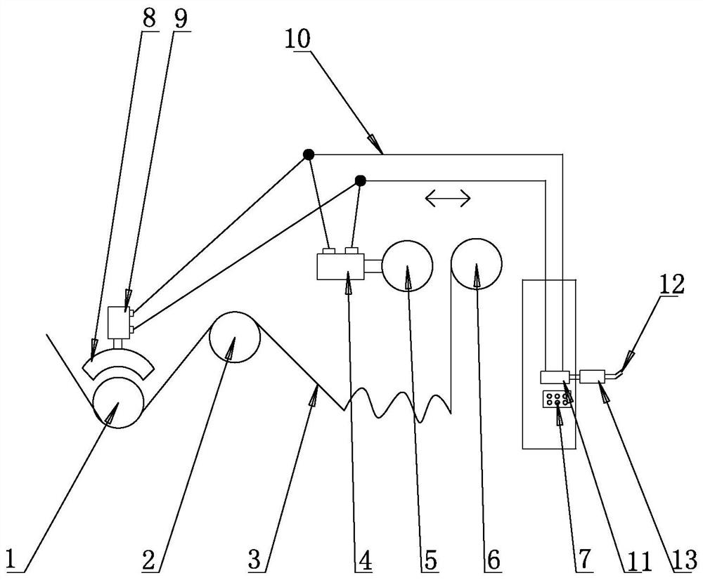
[0017] Such as figure 1 As shown, the embodiment of the recyclable pneumatic braking device of the present invention includes a textile machine, the textile machine is provided with a console 7, and one side of the console 7 is provided with a second traction roller 6, and the second traction roller 6 The side away from the console 7 is provided with a first traction roller 5, and the side of the first traction roller 5 away from the console 7 is provided with a cloth guide roller 1, and the cloth guide roller 1 is connected with a cylinder 9 through a brake friction block 8, so The console 7 described above is connected to the air cylinder 9 and the traction cylinder 4 through the air pipe 10 . The cloth 3 is connected with the second traction roller 6, between the emergency stop groove 2 and the cloth guide roller 1.

[0018] An emergency stop groove 2 is provided between the first traction roller 5 and the cloth guide roller 1 .

[0019] The console 7 is provided with a r...

Embodiment 2

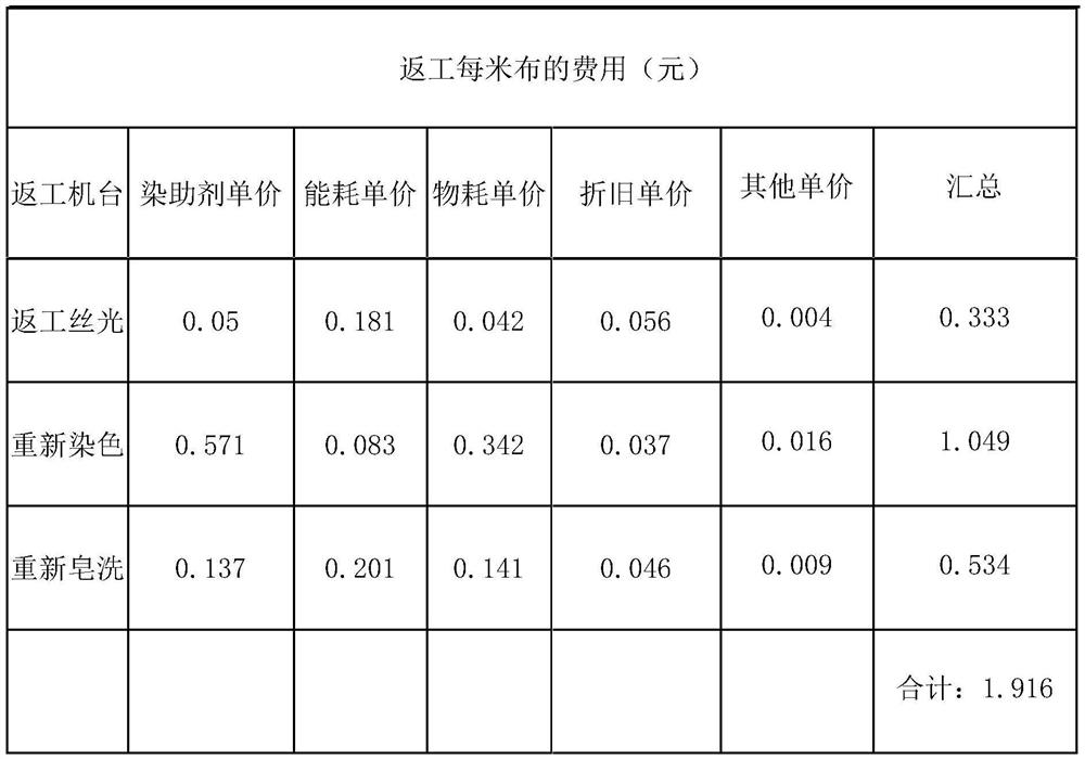
[0022] cost calculation:

[0023]

[0024] 1. It is calculated that the cost of reworking one meter of cloth3 is about 1.916 yuan

[0025] 2. After using the pneumatic brake, the number of head and tail creases is significantly reduced, the rework rate is reduced by 90%, the corresponding cost is also reduced, and the machine operation rate is increased.

[0026] 3. The self-made pneumatic brake can adjust the braking force and is not easy to be damaged. It only needs to replace the brake friction block 8, which costs about two yuan each.

[0027] Working process or working principle:

[0028] The external compressed air enters the pressure regulating valve 13 and the reversing valve 11 in turn through the air inlet 12, and is introduced into the cylinder 9 and the traction cylinder 4 through the air pipe 10, and the piston on the cylinder pushes the brake friction block 8 out to make the brake friction block 8 is tightly connected with the cloth guide roller 1 roll surfa...


PUM


Abstract

The invention relates to a pneumatic brake device capable of being circularly used, and belongs to the technical field of textile mechanical brake systems. The device comprises a textile machine, a control table is mounted on the textile machine, a second traction roller is arranged on one side of the control table, the side, away from the control table, of the second traction roller is provided with a first traction roller, the side, away from the control table, of the first traction roller is provided with a cloth guide roller, an air cylinder is connected to the cloth guide roller through abrake friction block, the control table is connected with an air cylinder and a traction air cylinder through an air pipe, through the airflow transmission, manpower can be replaced, rapid brake action is achieved, meanwhile, the pressure is set through a pressure adjusting valve, the mechanical wear brought by manual brake can be avoided, and the cloth quality is improved.

Description

technical field [0001] The invention relates to a recyclable pneumatic brake device, which belongs to the technical field of textile machinery brake systems. Background technique [0002] With the development of the trend, the number of weaves used in fabrics is getting higher and higher and the requirements of processing technology are constantly improving. High-weave fabrics are easy to fold when changing rolls and fabrics, resulting in irreparable defects. In order to prevent the fabric from folding when the roll is changed, it must be ensured that the fabric guide roller (the one in front of the feed trough) that drives the fabric cannot rotate when the roll is changed, or it is more rotating than other guide rollers. slow. [0003] In order to ensure this requirement, the use status of the brake device of the cloth guide roller is very important. There is a problem that the position of the original manual brake is a little far away from the operating table of the roll ...

Claims


Application Information

Patent Timeline
IPC IPC(8): B65H23/06B65H20/02
CPCB65H20/02B65H23/06B65H2404/165
Inventor 陈丰钢
Owner 鲁丰织染有限公司
Why Eureka
Try Eureka