Automatic light modulation device

An automatic dimming, optoelectronic technology, applied in the directions of installation, optics, optical components, etc., can solve the problem of undeveloped dimming devices and so on

Inactive Publication Date: 2008-12-17
XI'AN INST OF OPTICS & FINE MECHANICS - CHINESE ACAD OF SCI
View PDF3 Cites 0 Cited by
  • Summary
  • Abstract
  • Description
  • Claims
  • Application Information

AI Technical Summary

Problems solved by technology

[0002] When the observation instrument searches and aims at the moving target, it is hoped that the system can meet the changes of the external brightness and illuminance. Therefore, the observation instrument should have the corresponding dimming ability to meet the observation needs. Dimming device on the system

Method used


Image

  • Automatic light modulation device
  • Automatic light modulation device

Examples


Embodiment Construction

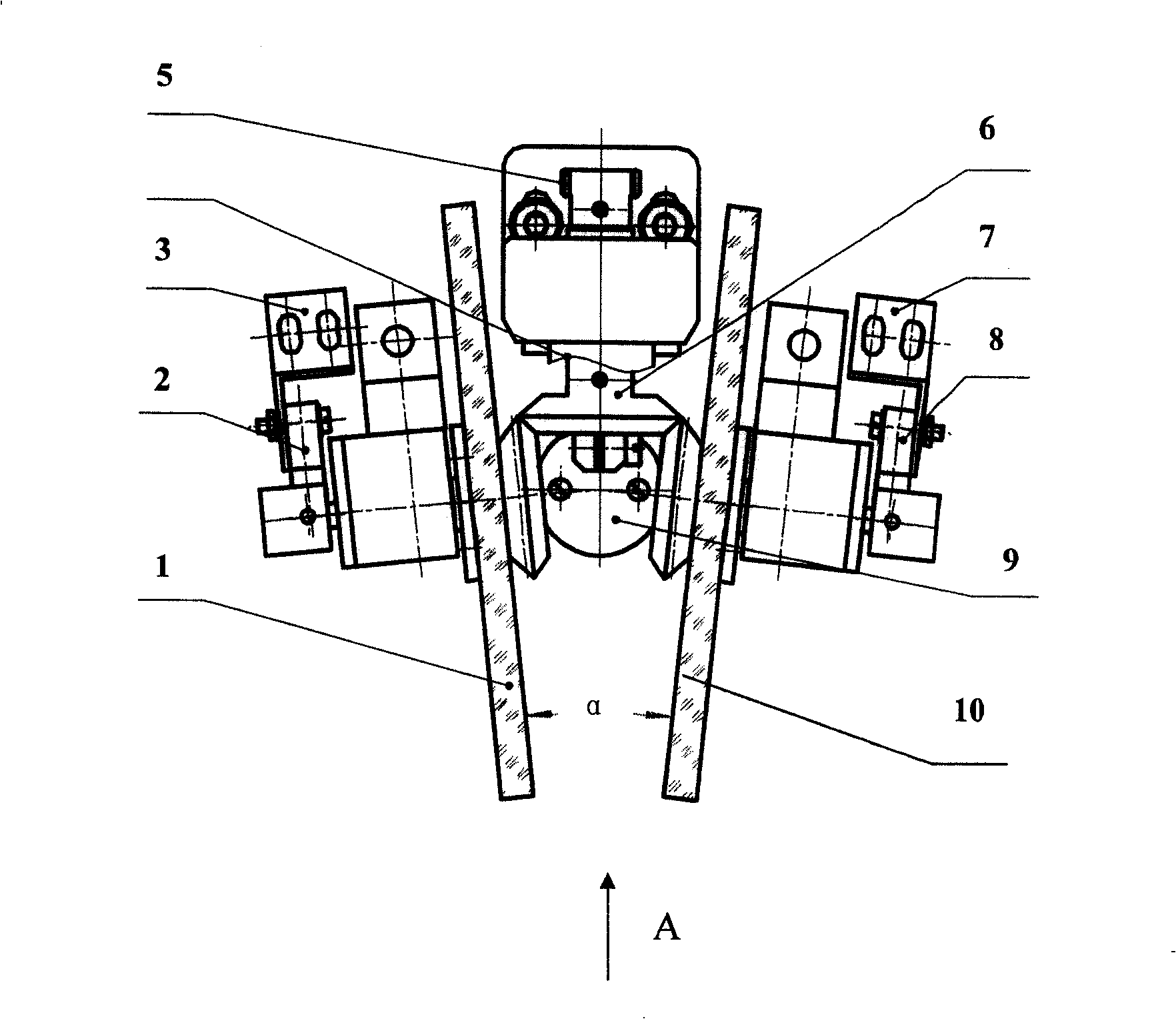
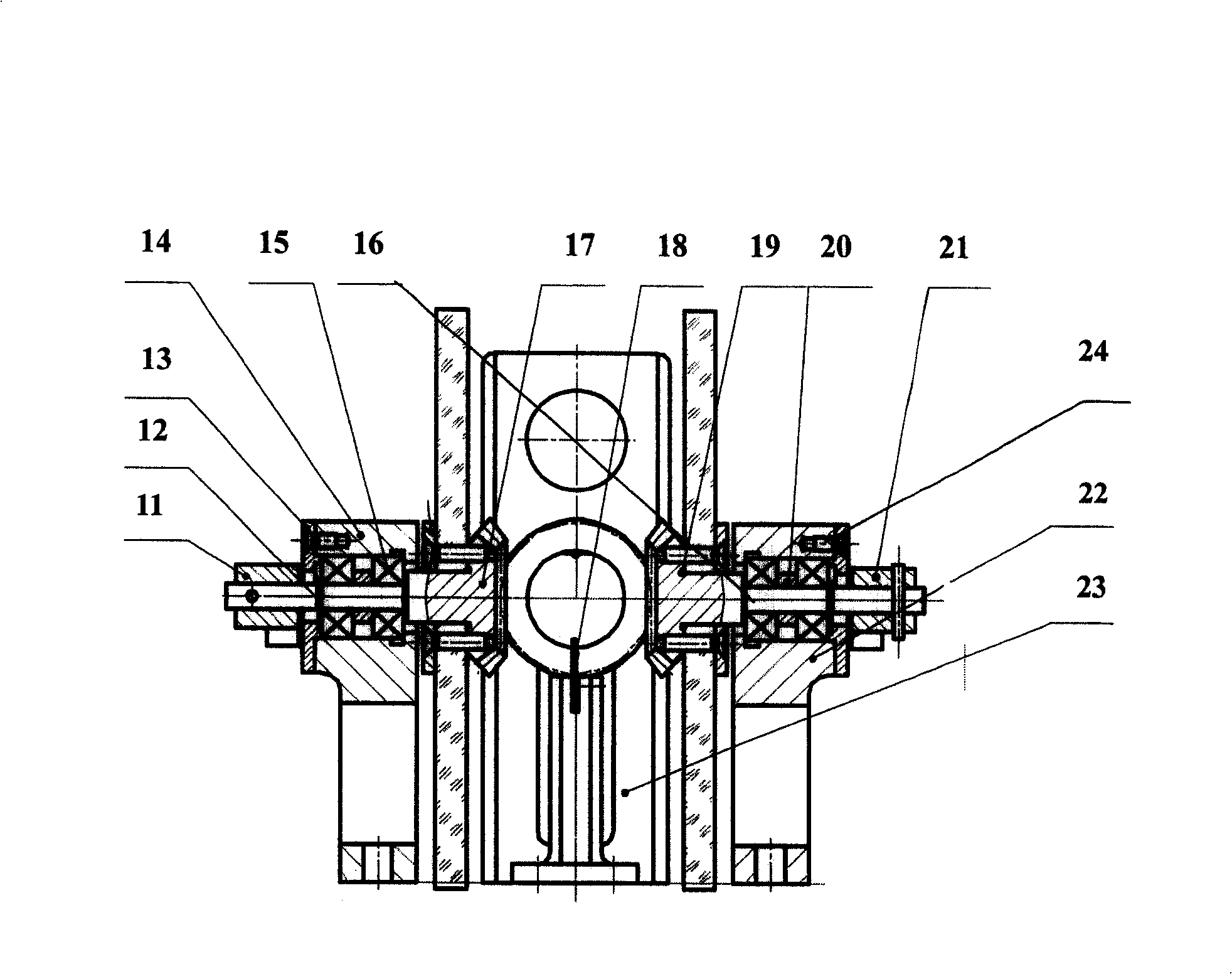
[0016] see figure 1 , 2 , the present invention includes symmetrical variable density discs 1, 10, driving bevel gear 6 and servo micromotor 4 that can drive the driving bevel gear 6. meshing, the angle α between the variable density discs 1 and 10 is 9-15°, preferably 12°; the two variable density discs 1 and 10 are respectively arranged on the shafts of the bevel gears 17 and 19, and the bevel gears 17 and 19 The shaft is connected with variable density discs 1, 10 through two bearing blocks 12, 16, which include bearing frames 14, 22, bearings 15, 20 and bearing caps 13, 24 respectively, and bearings 15, 20 are respectively arranged on In the bearing frame 14,22, bearing caps 13,24 are respectively arranged outside the bearing frame 14,22, and the shafts of the bevel gears 17,19 are respectively arranged on the bearings 15 and 20; The electric limit devices 3 and 7 are used to electrically limit the variable density discs 1 and 10 respectively through the electric limit d...


PUM


Abstract

The present invention relates to an automatically adjusting light device. The technic proposal includes that the device comprises variable density disks, a driving taper gear and a micro servo-motor for driving the driving taper gear, the variable density disks are engaged with the driving taper gear by the taper gear, and two variable density disks are provided, and symmetrically arranged on the two sides of the driving taper gear. The present invention has the advantages that the light-adjusting accuracy is high, the light-adjusting effect is good and the structure is compact.

Description

technical field [0001] The invention relates to an automatic dimming device. Background technique [0002] When the observation instrument searches and aims at the moving target, it is hoped that the system can meet the changes of the external brightness and illuminance. Therefore, the observation instrument should have the corresponding dimming ability to meet the observation needs. Dimming device on the system. Contents of the invention [0003] In order to solve the above-mentioned technical problems in the background technology, the present invention provides an automatic dimming device with high dimming precision, good dimming effect and compact structure. [0004] The technical solution of the present invention is: the present invention is an automatic dimming device. The gear meshes with the driving bevel gear, and there are two variable density discs, which are arranged symmetrically on both sides of the driving bevel gear. [0005] The variable density disk is ...

Claims


Application Information

Patent Timeline
Patent Type & Authority Patents(China)
IPC IPC(8): G02B7/00
Inventor 郝斌姜志超
Owner XI'AN INST OF OPTICS & FINE MECHANICS - CHINESE ACAD OF SCI
Why Eureka
Try Eureka