Conveying device, conveying acceleration decision method for conveying device
A conveying device and acceleration technology, which can be used in positioning devices, metal processing equipment, metal processing machinery parts, etc., and can solve problems such as increasing costs.
- Summary
- Abstract
- Description
- Claims
- Application Information
AI Technical Summary
Problems solved by technology
Method used
Image

Examples
no. 1 Embodiment
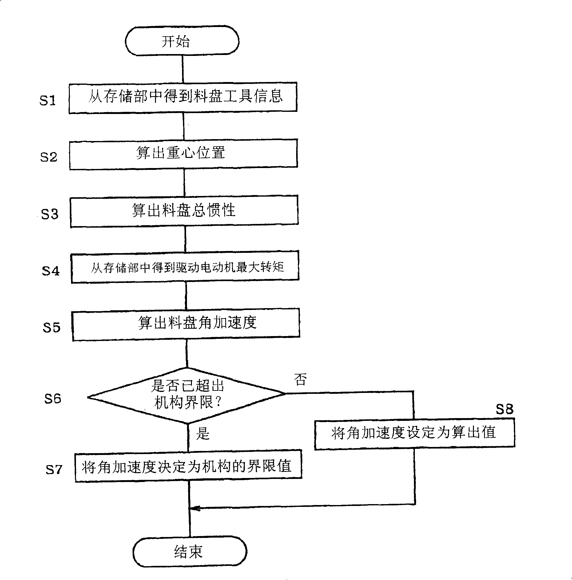
[0016] Refer below Figure 1 ~ Figure 3 A first embodiment in which the present invention is applied to a tool changing device comprising a turret-type tray will be described. In addition, the structure of the tool changer in this embodiment is the same as that disclosed in Japanese Patent Publication No. 7-80109, for example, and only the main parts related to the present invention will be described below.
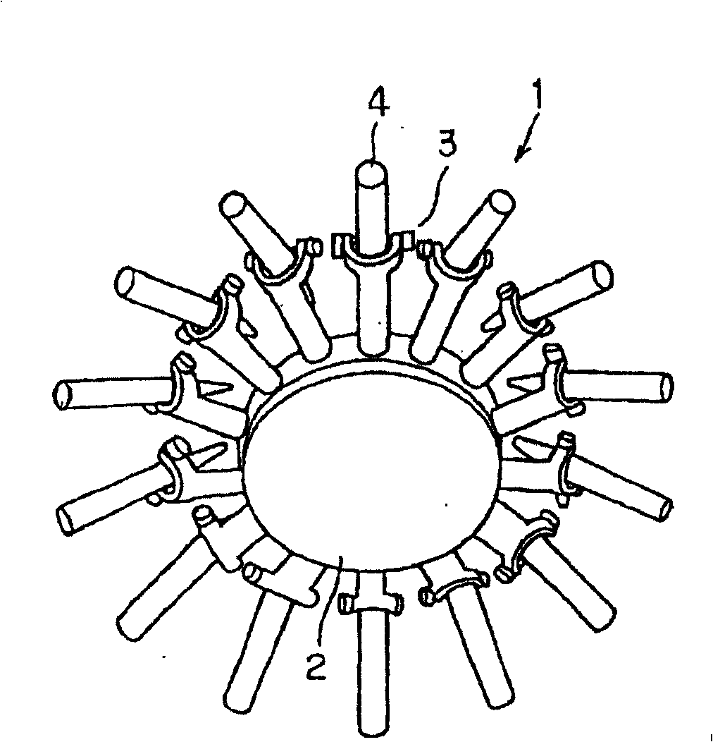
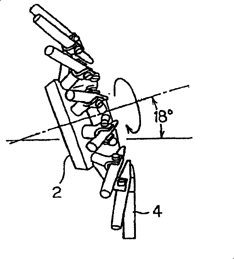
[0017] FIG. 2( a ) shows a perspective view in which the tool pallet (conveying unit) 1 incorporated in the tool changing device is taken out. The tool tray 1 is mounted on the outer peripheral portion of a substantially disc-shaped tray base 2, and a plurality of clamp arms 3 are formed in a radial shape. As shown in FIG. 4, at the front end of the clamp arm 3, in order to clamp the upper end side of the tool holder (transport object) 4 with the tool installed on the lower end side, the holding part 5 is formed in a U-shape. On both sides of the front end, support pins...
no. 2 Embodiment
[0044] 4 to 6 show the second embodiment of the present invention, the same parts as the first embodiment are given the same symbols, and their descriptions are omitted, and only the different parts will be described below. In the second embodiment, the main CPU 11 of the numerical control device 10 also considers the distribution state of the tools 4 arranged on the tool pallet 1 to determine the maximum rotational angular acceleration Amax.
[0045] FIG. 4 illustrates the influence of the rotation of the tray base 2 on the distribution balance of the tools 4 . The bottom in Fig. 4 becomes the direction of gravity action. As shown in Fig. 4(a), on the tray base 2, if the tool 4 at the position (A) is moved to the position (B) for tool exchange, the vicinity of the position (A) becomes the point of rotation. In the acceleration area, the vicinity of position (B) becomes the deceleration area of the rotary motion. Between the two becomes a constant velocity region.
[0046...
PUM
 Abstract
Description
Claims
Application Information
 - R&D Engineer
- R&D Manager
- IP Professional
- Industry Leading Data Capabilities
- Powerful AI technology
- Patent DNA Extraction
Browse by: Latest US Patents, China's latest patents, Technical Efficacy Thesaurus, Application Domain, Technology Topic.
© 2024 PatSnap. All rights reserved.Legal|Privacy policy|Modern Slavery Act Transparency Statement|Sitemap