
Height adjusting device for inlaid piece of mould

A height adjustment device and insert technology, applied in the field of molds, can solve the problems of material consumption, increased mold manufacturing costs, and difficult processing of cylinder 107, and achieve the effect of simple structure and convenient manufacture

Inactive Publication Date: 2009-01-21
HONG FU JIN PRECISION IND (SHENZHEN) CO LTD +1
View PDF12 Cites 0 Cited by
  • Summary
  • Abstract
  • Description
  • Claims
  • Application Information

AI Technical Summary

Problems solved by technology

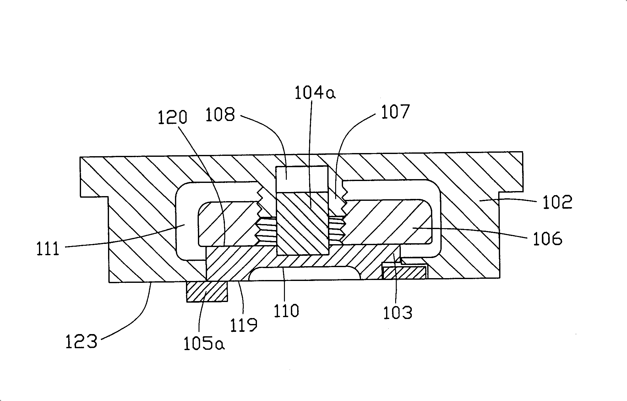
[0005] Although the above-mentioned insert adjustment structure solves the problem of adjusting the height of the insert, it is necessary to set a cylinder 107 in the cavity 111 of the template 102 to match the through hole in the spacer 106, and to set a thread on the cylinder 107. A through hole is provided on the spacer 106 and a screw thread is set in the through hole, thus causing the structure of the spacer 106 and the template 102 to be more complicated
When making the template, the cylinder 107 in the cavity 111 is not easy to process, and consumes materials, and the processing steps increase, which increases the manufacturing cost of the mold

Method used


Image

  • Height adjusting device for inlaid piece of mould
  • Height adjusting device for inlaid piece of mould
  • Height adjusting device for inlaid piece of mould

Examples


Embodiment approach

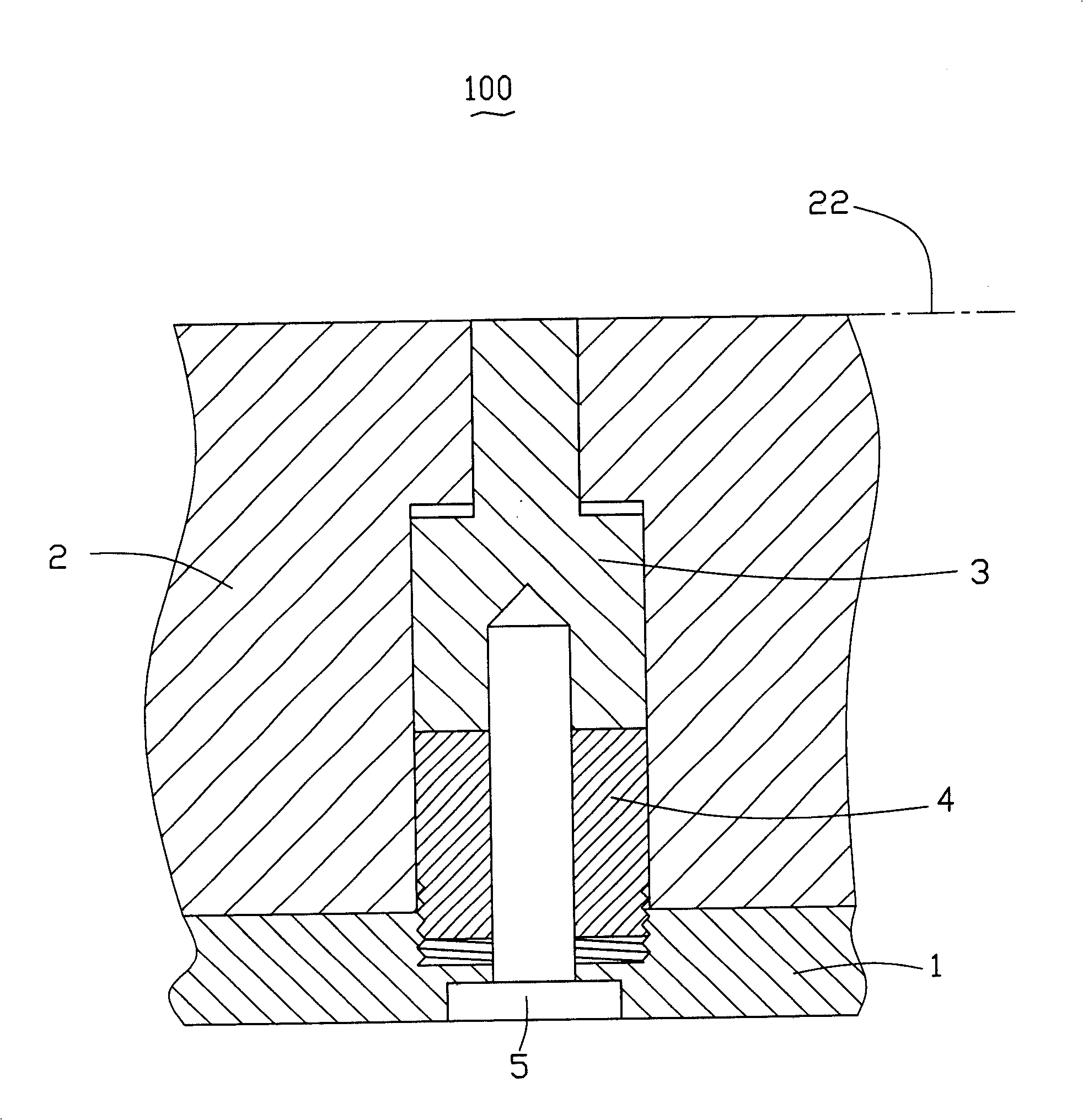
[0016] like figure 2 As shown, the height adjusting device 100 of the mold insert according to the first embodiment of the present invention includes a template 1 , a module 2 , an insert 3 , a spacer 4 and a screw 5 . The module 2 is installed on the template 1 , the insert 3 and the spacer 4 placed below it are installed in the module 2 and the template 1 , and the screws 5 are used to fix the insert 3 in the module 2 .

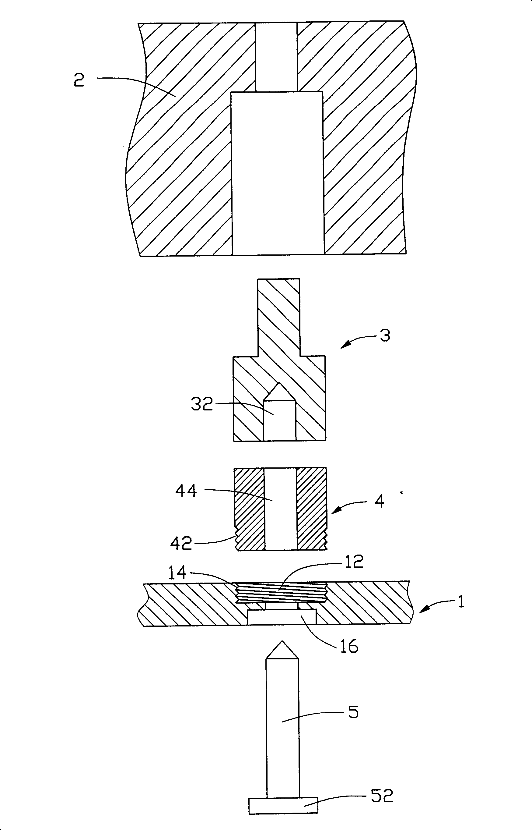
[0017] like image 3 As shown, a circular hole 12 is opened on the template 1, and the inner surface of the hole 12 is provided with an internal thread 14; the spacer 4 is cylindrical, and its lower end is provided with an external thread 42. In addition, coaxial circular holes 32 , 44 and 16 are provided on the insert 3 , spacer 4 and template 1 respectively, so that the screws 5 can be inserted when the insert 3 is fixed. The hole 32 on the insert 3 is a blind hole, and its inner surface is provided with an internal thread (not shown) that matches the ...


PUM


Abstract

The mold insert height regulator includes mold board, insert and cushion block. The insert and the cushion block are installed onto the mold board, and the insert is set on the cushion block. The mold board has screw hole for the cushion block with outer thread to be screwed in. regulating the relative height of the cushion block to the mold board can alter the height of the mold insert. The height regulator is simple in structure and easy to operate, and may result in lowered mold cost.

Description

【Technical field】 [0001] The invention relates to molds, in particular to a height adjusting device for mold inserts. 【Background technique】 [0002] The mold core is the forming part of the mold, including the upper mold core and the lower mold core, wherein the upper mold core and the lower mold core are respectively installed on the upper and lower templates to form the shape of the product together. In order to ensure the molding accuracy, the material of the mold core is selected according to the specific product type and mold condition, and the mold steel is selected. The molding surface of the mold core is generally processed by electrode discharge, wire cutting and CNC (computer numerical control). [0003] For some mold cores with a part of the molding surface that is difficult to process, an insert with the local surface can be made separately and embedded on the mold core, or inserts can be inlaid at the position where the mold core is easy to wear, such as the co...

Claims


Application Information

Patent Timeline
Patent Type & Authority Patents(China)
IPC IPC(8): B29C33/12
Inventor 杜健生
Owner HONG FU JIN PRECISION IND (SHENZHEN) CO LTD
Learn More