
Metal plate bending deformation machining die

A technology for bending deformation and processing molds, applied in the field of sheet metal processing, can solve the problems of springback of thin metal sheets, uneven pressure direction and size, reducing molding quality, etc., and achieve the effect of avoiding springback

Active Publication Date: 2020-09-25
东莞西迈金属材料有限公司
View PDF6 Cites 0 Cited by
  • Summary
  • Abstract
  • Description
  • Claims
  • Application Information

AI Technical Summary

Problems solved by technology

[0004] The invention provides a metal sheet metal bending deformation processing die, the purpose is to solve the following problems existing when the metal sheet is bent and deformed by die punching: (1) Since the metal sheet itself is relatively light, after the die stamps it, Since the air between the plate and the mold is evacuated, the plate will be tightly attached to the surface of the mold under the action of air pressure. At this time, the stamped plate needs to be removed manually. The shape of the plate is easy to be damaged during the manual removal process. Reduced forming quality; (2) When the existing mold is stamping and forming the metal sheet, the pressure direction and size of the metal sheet are uneven, resulting in partial springback of the formed metal sheet after the stamping is completed , which also reduces the forming quality of sheet metal

Method used


Image

  • Metal plate bending deformation machining die
  • Metal plate bending deformation machining die
  • Metal plate bending deformation machining die

Examples


Embodiment Construction

[0026] The embodiments of the present invention will be described in detail below with reference to the accompanying drawings, but the present invention can be implemented in many different ways defined and covered by the claims.

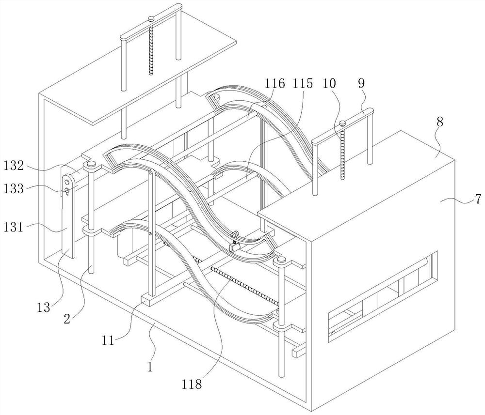
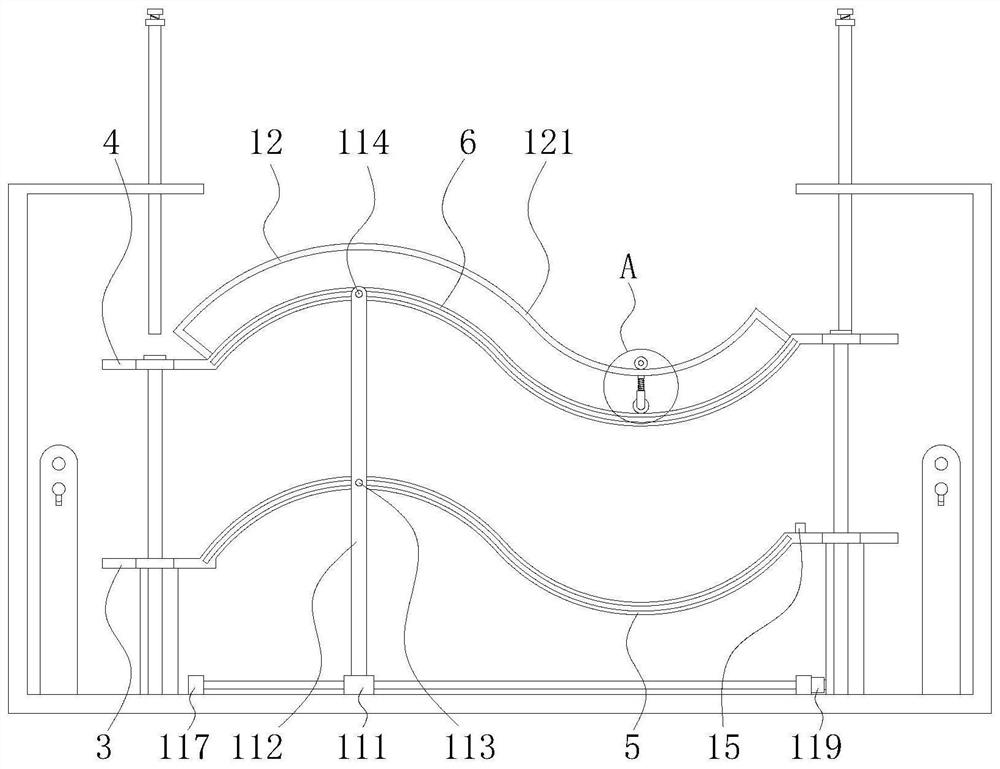
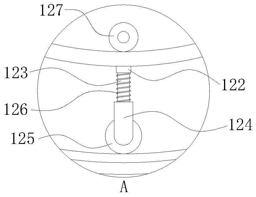
[0027] Such as Figure 1 to Figure 5 As shown, this embodiment provides a metal plate bending deformation processing mold, including a horizontal bottom plate 1, four guide rods 2 are vertically fixedly installed on the bottom plate 1, and two pressure bearing plates are fixedly installed horizontally on the guide rod 2 3. Two pressure-applying plates 4 located above the pressure-bearing plate 3 and parallel to the pressure-bearing plate 3 are vertically slidably installed on the guide rod 2 . Two pressure-bearing strips 5 with the same shape and size and corresponding positions are fixedly installed between the two pressure-bearing plates 3, and two pressure-bearing strips 5 that cooperate with the pressure-bearing strips 5 and correspond to the po...


PUM


Abstract

The invention belongs to the technical field of plate machining, and particularly relates to a metal plate bending deformation machining die. The metal plate bending deformation machining die comprises a horizontal bottom plate, guide rods are installed on the bottom plate, pressure bearing plates are installed on the guide rods, and pressure applying plates are installed on the guide rods in a sliding mode; pressure bearing strips are fixedly installed between the pressure bearing plates, and pressure applying strips are fixedly installed between the pressure applying plates; a vertical plateis mounted on the bottom plate, and a horizontal plate is mounted at the top end of the vertical plate; a door-shaped frame is slidably installed on the horizontal plate, a first lead screw is vertically and rotationally installed on the horizontal plate, and the first lead screw penetrates through the door-shaped frame and is matched with the door-shaped frame through threads; a first re-pressing mechanism is mounted on the bottom plate; a second re-pressing mechanism is mounted on the pressure applying strips; and a tensioning mechanism is mounted between the vertical plate and the pressurebearing plate. When the metal plate bending deformation machining die is used for bending and shaping a metal plate, pressure which is constant in size and always perpendicular to the surface of themetal plate can be applied to the edge of the metal plate, and the metal plate is prevented from rebounding; and the shape of the metal plate cannot be damaged during material taking.

Description

technical field [0001] The invention belongs to the technical field of plate processing, and in particular relates to a metal plate bending deformation processing mold. Background technique [0002] Metal sheet is a common building component and manufacturing and processing accessory. In actual use, the metal sheet needs to be processed into different shapes. The main method is to stamp a flat metal sheet through a mold to make it a fixed shape. In the actual processing and production process, when the metal sheet is bent and deformed by die stamping, there will be the following problems: (1) Since the metal sheet itself is relatively light, after the die stamps it, due to the gap between the sheet and the die The air is evacuated, and the plate will be tightly attached to the surface of the mold under the action of air pressure. At this time, the stamped plate needs to be removed manually. The shape of the plate is easily damaged during the manual removal process, which re...

Claims


Application Information

Patent Timeline
Patent Type & Authority Applications(China)
IPC IPC(8): B21D37/12B21D11/22B21D11/00
CPCB21D37/12B21D11/22B21D11/00
Inventor 刘静
Owner 东莞西迈金属材料有限公司
Learn More