
Hard disk and press block positioning structure thereof

A positioning structure, hard disk technology, applied in the direction of recording information storage, instruments, etc., can solve the problems of not providing positioning, vibration, etc., to achieve the effect of reducing vibration and enhancing the positioning effect

Inactive Publication Date: 2009-02-04
YITUO SCI & TECH CO LTD SHENZHEN
View PDF3 Cites 0 Cited by
  • Summary
  • Abstract
  • Description
  • Claims
  • Application Information

AI Technical Summary

Problems solved by technology

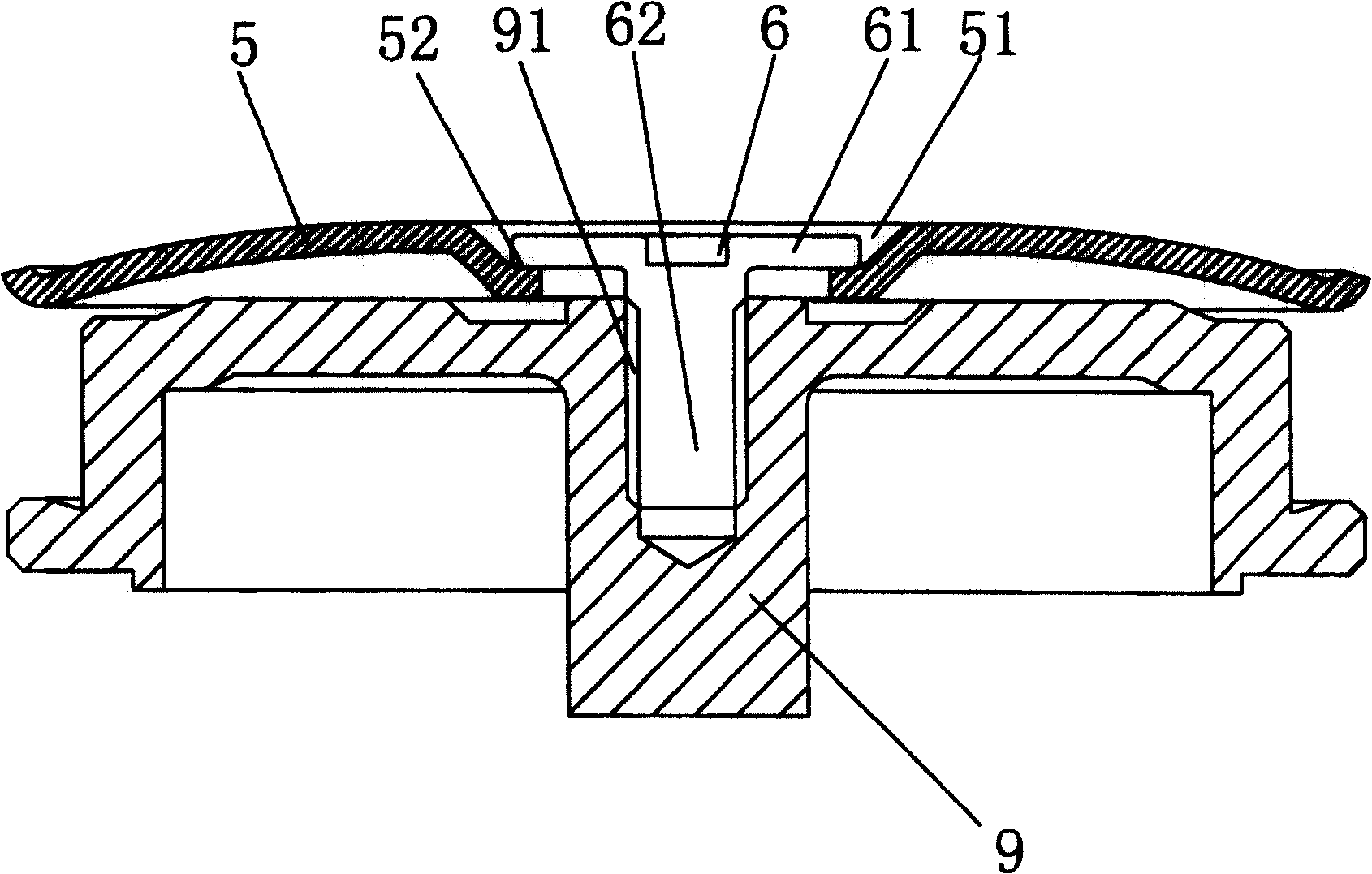
However, this kind of hard disk has the following disadvantages: no positioning is provided when the pressing block 5 and the motor 9 are installed, so that the center of the pressing block 5 and the center of the motor 9 deviate, and the motor 9 rotates eccentrically, thereby causing vibration

Method used


Image

  • Hard disk and press block positioning structure thereof
  • Hard disk and press block positioning structure thereof
  • Hard disk and press block positioning structure thereof

Examples


Embodiment Construction

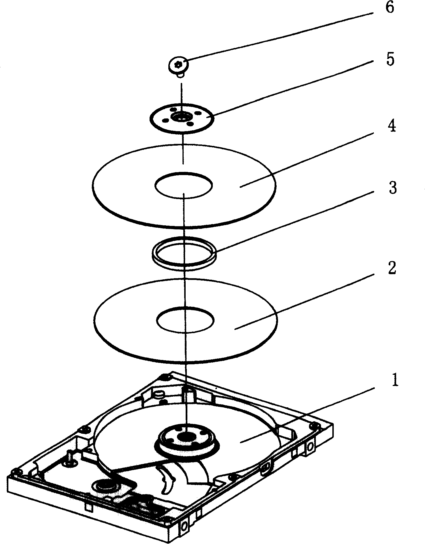
[0019] see Figure 2 to Figure 9 , The hard disk of the present invention includes a base 1 , a first disc 2 , a spacer 3 , a second disc 4 , a pressing block 5 and a fastener 6 .

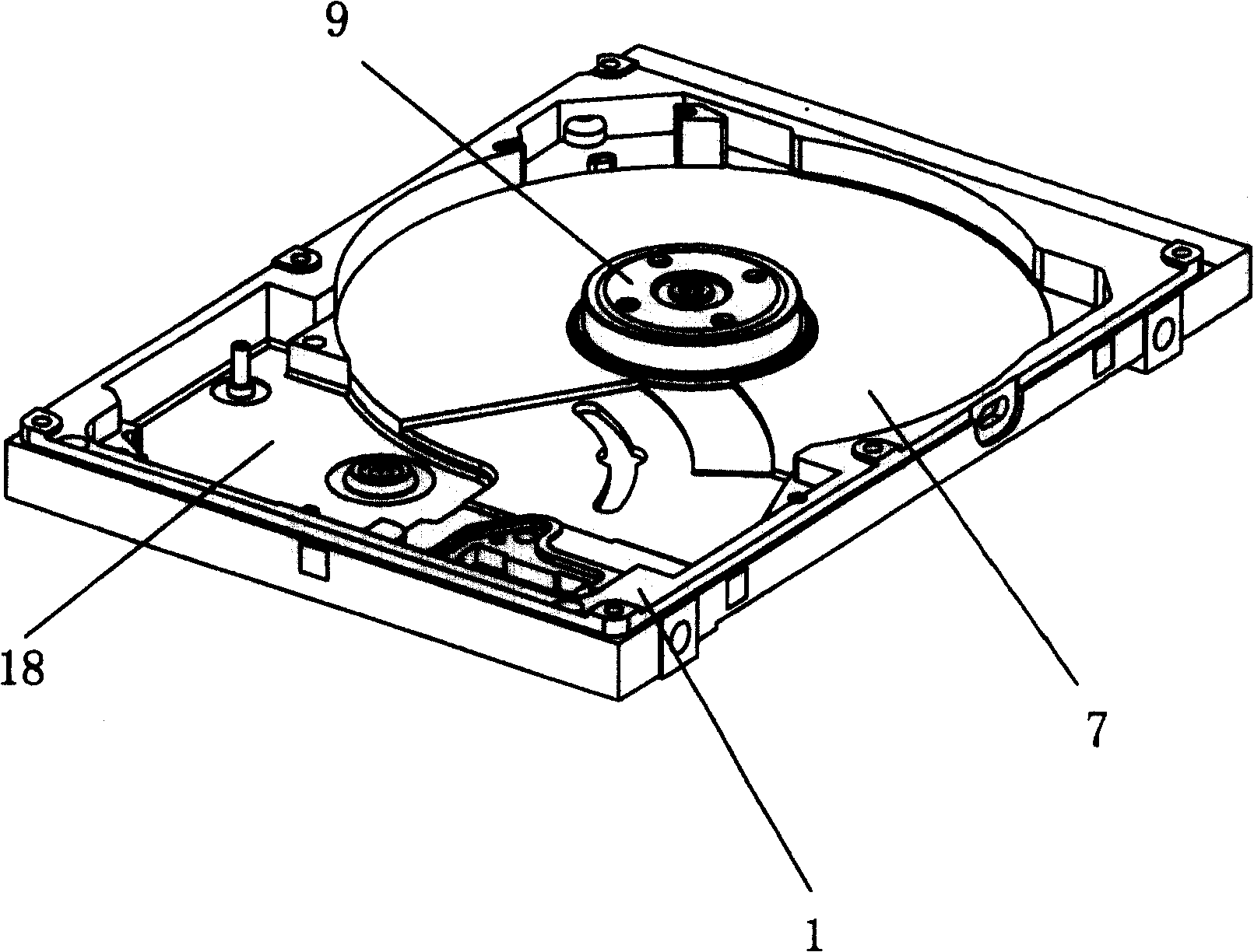
[0020] see image 3 and Figure 9 The base 1 is provided with a disk placement area 7 and a magnetic head assembly installation area 18, a cylindrical bearing motor 9 is installed at the center of the disk placement area 7, and a magnetic head assembly 19 and a magnetic head assembly are installed in the magnetic head assembly installation area 18. block assembly 30 .

[0021] see Figure 4 , the bearing motor 9 has a smooth top surface 16, a groove 10 is recessed from the central position of the top surface 16 along the axial direction of the motor 9, and a groove 10 is formed vertically from the central position of the groove 10 along the axial direction The positioning boss 11 extends upwards, and the top surface 111 of the positioning boss 11 is higher than the top surface 16 of the motor. ...


PUM


Abstract

This invention discloses a localization structure of a disc holddown including a column motor, a holddown, a fastener and a disc covered on the motor, in which, the center of the motor is set with a localizing convex desk, a screw thread hole is set at the center of the desk, said holddown is set on the disk, said central position has a through ladder hole, said fastener has a pole part with a head of large diameter at the top and screw thread at the bottom, and the fastener is set with a localizing ring surrounding the pole, the head of the fastener is supported on the stage of the ladder hole and the localizing ring is blocked between the outside wall of the convex desk and the wall of the ladder hole and the screw thread of the fastener is matched with that of the screw thread hole to realize double localization.

Description

technical field [0001] The invention relates to the field of hard disks. Background technique [0002] see figure 1 , the existing hard disk includes a cylindrical bearing motor 9, a briquetting block 5 and a fastening screw 6, the liquid dynamic bearing motor 9 is installed in the central position of the hard disk base, the central position of the briquetting block 5 is provided with a stepped hole 51, and the tightening The nut 61 of the fastening screw 6 rests on the step surface 52 of the stepped hole 51 , and the screw rod 62 of the fastening screw 6 is threadedly engaged with the threaded hole 91 of the motor 9 , so that the briquetting block 5 is mounted on the motor 9 . However, this kind of hard disk has the following disadvantages: no positioning is provided when the pressing block 5 and the motor 9 are installed, so that the center of the pressing block 5 deviates from the center of the motor 9, and the motor 9 rotates eccentrically, thereby causing vibration. ...

Claims


Application Information

Patent Timeline
Patent Type & Authority Patents(China)
IPC IPC(8): G11B17/028
Inventor 王华
Owner YITUO SCI & TECH CO LTD SHENZHEN
Learn More