Supercharge Your Innovation With Domain-Expert AI Agents!

Orbiting vane compressor and piston thereof

一种压缩机、活塞阀的技术,应用在双活塞阀领域,能够解决产生噪声、降低装配效率、不易于簧片阀安装等问题

Inactive Publication Date: 2009-03-11
LG ELECTRONICS INC
View PDF4 Cites 0 Cited by
  • Summary
  • Abstract
  • Description
  • Claims
  • Application Information

AI Technical Summary

Problems solved by technology

Therefore, it is not easy to install the reed valve at the inner outlet and the outer outlet which are arranged adjacent to each other, thereby reducing assembly efficiency
In addition, when the reed valve is working, the reed valve repeatedly collides with the auxiliary bearing, resulting in noise

Method used


Image

  • Orbiting vane compressor and piston thereof
  • Orbiting vane compressor and piston thereof
  • Orbiting vane compressor and piston thereof

Examples


Embodiment Construction

[0044] Hereinafter, preferred embodiments of the present invention will be described in detail with reference to the accompanying drawings.

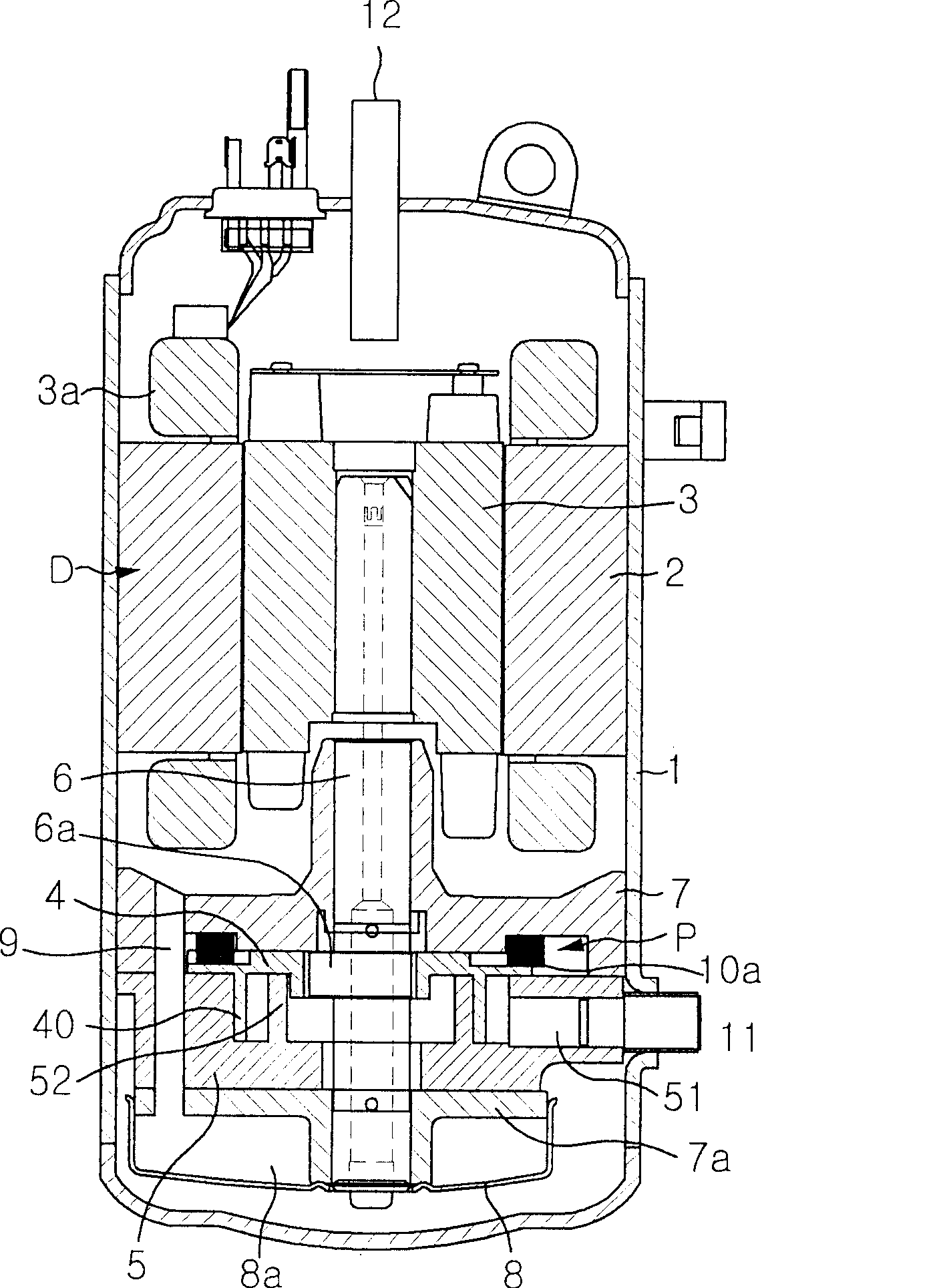
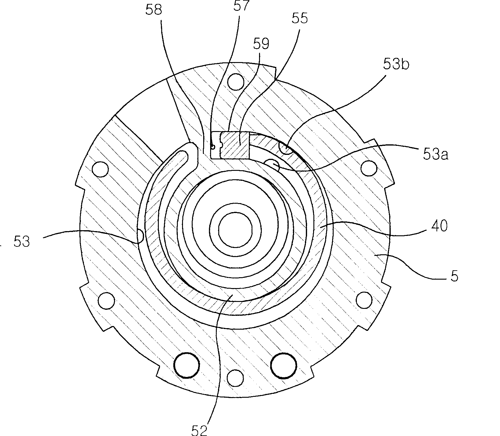
[0045] Generally, a rotary orbiting vane compressor includes a driving unit D and a compression unit P disposed below the driving unit D. As shown in FIG. The compression unit P is connected to the drive unit D via a shaft 6 . The rotary shaft 6 has opposite ends supported by a main bearing 7 and an auxiliary bearing 7 a located at upper and lower portions of the compression unit P. As shown in FIG. Such as image 3 As shown, the auxiliary bearing 7a has an inner outlet 53a and an outer outlet 53b extending through the cylinder 5 (see figure 1 ).

[0046] Figure 5 A perspective view showing the bottom of the auxiliary bearing 7a of the orbiting vane compressor to which the double piston valve according to the present invention is applied.

[0047] Such as Figure 5 As shown, the dual piston valve includes a valve housing 110 forme...


PUM


Abstract

Disclosed herein is a dual-piston valve for orbiting vane compressors. The dual-piston valve comprises a valve housing having a pair of piston operation spaces defined therein and a pair of pistons disposed in the piston operation spaces of the valve housing such that the pistons can be vertically moved to open or close inner and outer outlet ports formed at a cylinder. At one end of the valve housing are formed a pair of through-holes, which communicate with the piston operation spaces, respectively. Gas outlet ports are formed at opposite longitudinal sides of the valve housing. With the above-stated construction, compressed refrigerant gas is properly discharged, and therefore, performance of the orbiting vane compressor is prevented from being deteriorated due to over-compression loss of refrigerant gas.

Description

technical field [0001] The present invention relates to an orbiting vane compressor, and in particular to a dual-piston valve for an orbiting vane compressor which can be easily and conveniently mounted on an orbiting vane compressor The inner outlet and outer outlet port of the machine, and can prevent the performance deterioration of the orbiting vane compressor due to the over-compression loss of the refrigerant gas. Background technique [0002] Generally, an orbiting vane compressor is configured to compress refrigerant gas introduced into a cylinder by orbiting movement of orbiting vanes in the cylinder having an inlet. Different types of orbiting vane compressors have been proposed and classified according to their shape. [0003] figure 1 It is a longitudinal sectional view showing the overall structure of a conventional rotary-type orbiting vane compressor. Such as figure 1 As shown, the drive unit D and the compression unit P disposed below the drive unit D are...

Claims


Application Information

Patent Timeline
Patent Type & Authority Patents(China)
IPC IPC(8): F04C29/12
CPCF04C29/126F04C18/04F04C23/008
Inventor 黄善雄刘东原
Owner LG ELECTRONICS INC
Features
  • R&D
  • Intellectual Property
  • Life Sciences
  • Materials
  • Tech Scout
  • Unparalleled Data Quality
  • Higher Quality Content
  • 60% Fewer Hallucinations
Learn More