Optical object distance simulator

An analog device, optical technology, applied in the field of object distance devices, can solve the problems of inconvenient operation, large measurement space, and uneconomical, etc., and achieve the effect of increasing detection speed and good heat dissipation effect

Inactive Publication Date: 2009-03-11
YOUNGTEK ELECTRONICS
View PDF6 Cites 0 Cited by
  • Summary
  • Abstract
  • Description
  • Claims
  • Application Information

AI Technical Summary

Problems solved by technology

[0003] However, since the actual object distance d between the camera lens 3a to be tested and the chart 2a is too long, the overall measurement space is too large, so it is not only uneconomical, but also causes a lot of inconvenience in operation

Method used


Image

  • Optical object distance simulator
  • Optical object distance simulator

Examples


Embodiment Construction

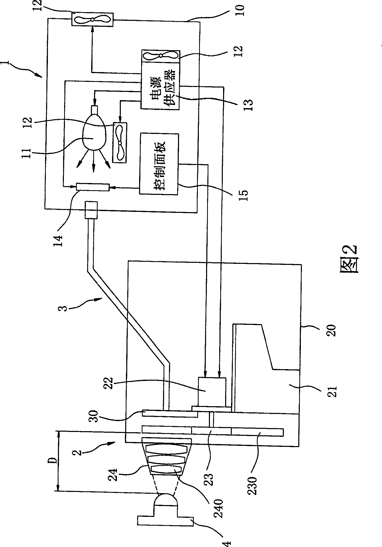
[0027] Please refer to FIG. 2 , which is a schematic structural diagram of the optical object distance simulation device of the present invention. It can be seen from the figure that the optical object distance simulation device disclosed in the present invention includes: a control unit 1 , an object distance simulation unit 2 and a light guide unit 3 .

[0028] The control unit 1 includes: a first housing 10, a light emitting element 11 disposed in the first housing 10, a heat dissipation element 12, a power supply 13, a color filter element (color filter) 14 and a control Panel 15. Wherein, the heat dissipation element 12 can be arranged on a side close to the light emitting element 11, and the heat dissipation element 12 can also be arranged (embedded) on the first housing 10 to dissipate heat from the light emitting element 11 or the control unit. 1 The heat generated by other heat sources.

[0029] In addition, the power supply 13 can be used to supply the power source...


PUM


Abstract

An object distance simulation device of optical type is prepared as setting lens module formed by multiple lens between a graphical chart and a camera lens to be tested for generating effect of simulating actual object distance so as to decrease measurement space and setting heat radiation element near to element building up heat for making said device have excellent heat radiation effect.

Description

technical field [0001] The invention relates to an optical object distance simulation device, in particular to a device for shortening the object distance between a camera lens to be tested and a detection chart by simulating the object distance. Background technique [0002] Please refer to FIG. 1 , which is a schematic diagram of a known camera lens inspection device. It can be seen from the figure that first a pair of light-emitting elements 1a project light beams onto a chart 2a, and then adjust the real object distance between a camera lens 3a to be tested and the chart 2a according to different test requirements. )d to achieve the purpose of detecting the camera lens 3a to be tested. In addition, the effective field of view (Field of View, FOV) of the camera mirror 3a under test with respect to the graph 2a is shown by the dotted line in the figure. [0003] However, since the actual object distance d between the camera lens 3a to be tested and the chart 2a is too lo...

Claims


Application Information

Patent Timeline
Patent Type & Authority Patents(China)
IPC IPC(8): G01M11/00
Inventor 汪秉龙王志明陈桂标郭国隆
Owner YOUNGTEK ELECTRONICS
Why Eureka
Try Eureka