Tilt ball-sliding contact switch

A sliding contact and ball technology, applied in the direction of electric switches, electrical components, circuits, etc., can solve the problems of small dynamic range of contact switches, unstable switch operation, poor contact stability, etc., to achieve stable and firm contact, prevent interference, and facilitate changes Effect

Inactive Publication Date: 2009-06-03
朱成辉
View PDF5 Cites 0 Cited by
  • Summary
  • Abstract
  • Description
  • Claims
  • Application Information

AI Technical Summary

Problems solved by technology

[0002] Inclined ball contact switch is a necessary device to start the control signal by sensing the change of equipment or angle. It is widely used in the control devices related to vibration, tilt and trigger of electronic products such as lamps, fans, anti-theft and toys. However, the currently used inclined ball contact switch has a small dynamic range, poor conduction, and poor contact stability. When a slight vibration occurs, it is prone to instant disconnection, and the switch operation is very unstable, which is difficult to meet the needs of consumers.

Method used


Image

  • Tilt ball-sliding contact switch
  • Tilt ball-sliding contact switch
  • Tilt ball-sliding contact switch

Examples


Embodiment 1

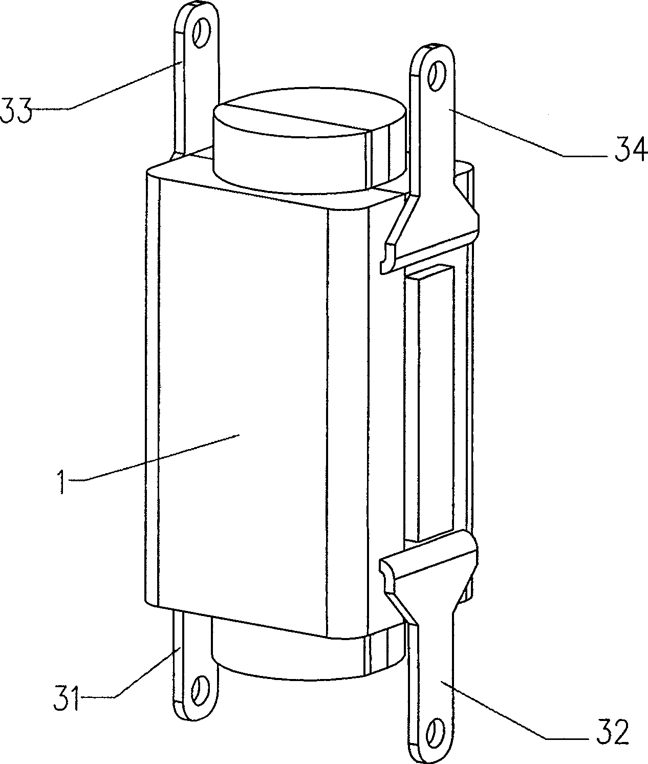
[0028] Such as figure 1 As shown, the present invention includes a housing 1 , a ball 2 and a first contact terminal 31 , a second contact terminal 32 , a third contact terminal 33 and a fourth contact terminal 34 pierced on the housing 1 .

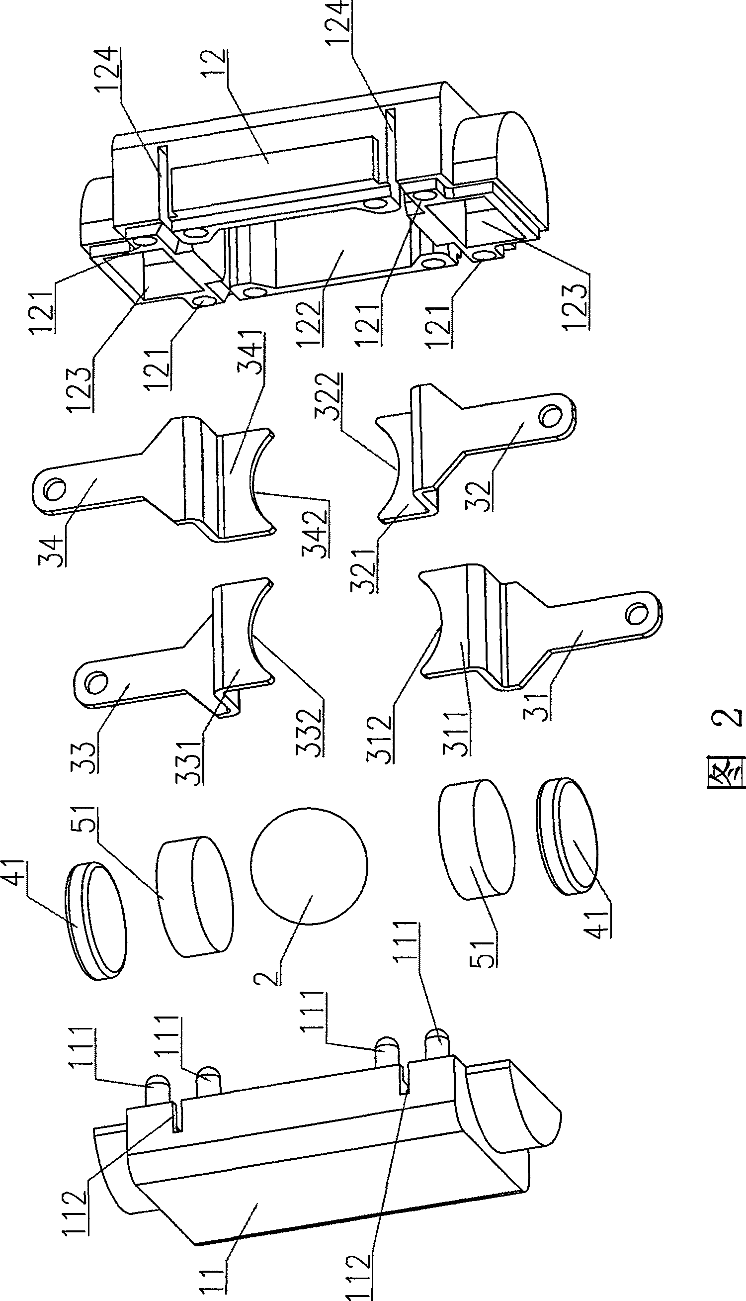
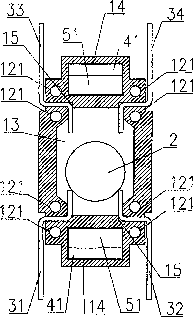
[0029] As shown in Figure 2, image 3 and Image 6 As shown, wherein, the housing 1 is assembled by the left half shell 11 and the right half shell 12, the left half shell 11 is provided with a positioning pin 111, and the right half shell 12 is provided with a positioning hole 121 matched with the positioning pin 111 , the left half-shell 11 and the right half-shell 12 are positioned by the cooperation of the positioning pin 111 and the positioning hole 121, and the upper and lower parts of the left half-shell 11 are respectively provided with a left half chamber (not shown) and a left half magnet chamber ( Not shown in the figure), the upper and lower parts of the right half shell 12 are respectively provided with a right half chamber...

Embodiment 2

[0038] Such as Figure 7 As shown, this embodiment is only provided with two contact terminals, that is, the first contact terminal 31 and the second contact terminal 32 , and other structures are the same as those of the first embodiment. Ball 2 has the following two stable states under the action of gravity and magnet attraction:

[0039] a. The ball 2 straddles between the arc-shaped notch 312 of the first supporting leg 311 and the arc-shaped notch 322 of the second supporting leg 321 , and the first contact terminal 31 and the second contact terminal 32 are in a conductive state.

[0040]b. There is a gap between the ball 2 and the first support leg 311 and the second support leg 321 , and the first contact terminal 31 and the second contact terminal 32 are disconnected.

[0041] When the inclination angle of the housing 1 changes continuously, the ball 2 switches back and forth between the above two stable states. The principle of its state conversion is basically the ...


PUM


Abstract

This invention open a tilt ball sliding contact switch, which includes Shell and Shell internal capacity located in the ball room, set up in the bottom of the shell of a first contact terminal, the second contact terminal, the first terminal contacts, in the second terminal capacity indoor contact with the respective first supporting leg, the second supporting leg, when the ball rolling at first and second supporting leg on the supporting leg will be the first contact terminal and the second terminal on-contact, when Support feet from the first ball and the second supporting leg terminal will be the first contact with the second contact terminals disconnect, in the lower part of a shell magnet, the magnet make the suction ball trundle the first and second supporting leg Support. It uses a suction adsorption ball magnet, increasing the Shell tilt angle, the ball reback and have more stable and prevent vibration limited interference.

Description

1. Technical field: [0001] The invention relates to a switch capable of sensing angle changes, in particular to an inclined ball sliding contact switch. 2. Background technology: [0002] Inclined ball contact switch is a necessary device to start the control signal by sensing the change of equipment or angle. It is widely used in the control devices related to vibration, tilt and trigger of electronic products such as lamps, fans, anti-theft and toys. However, the currently used inclined ball contact switch has a small dynamic range, poor conduction, and poor contact stability. When a slight vibration occurs, it is prone to instant disconnection, and the switch operation is very unstable, which is difficult to meet the needs of consumers. 3. Contents of the invention: [0003] In order to overcome the deficiencies of the prior art, the purpose of the present invention is to provide a kind of inclined ball sliding contact switch with stable contact, which can prevent the i...

Claims


Application Information

Patent Timeline
Patent Type & Authority Patents(China)
IPC IPC(8): H01H35/02
Inventor 朱成辉
Owner 朱成辉
Why Eureka
Try Eureka