
Production positioning structure of zipper attached with drawing head

A technology of attaching sliders and zippers, applied in the direction of sliding fastener components, applications, fasteners, etc., can solve the problems of lack of zipper strips, displacement of zipper strips, and affecting positioning accuracy, so as to reduce accidental pulling of the slider probability, the effect of improving the yield rate

Inactive Publication Date: 2009-06-10
UNITECH ZIPPER & MACHINERY
View PDF6 Cites 0 Cited by
  • Summary
  • Abstract
  • Description
  • Claims
  • Application Information

AI Technical Summary

Problems solved by technology

[0005] Although the above-mentioned feeding positioning mechanism can use the movable plate to position the zipper cloth strip with the slider before shooting, when the movable plate rises vertically, the feeding positioning mechanism will lack to prevent the zipper cloth strip from means of displacement, which may cause displacement of the zipper strip during this time
On the other hand, when the movable plate rises vertically, the front end surface of the movable plate may accidentally pull the slider of the zipper cloth, which may also cause the displacement of the zipper cloth
In this way, the above-mentioned reasons all may affect the positioning accuracy of the zipper cloth strip entering the combined mold subsequently

Method used


Image

  • Production positioning structure of zipper attached with drawing head
  • Production positioning structure of zipper attached with drawing head
  • Production positioning structure of zipper attached with drawing head

Examples


Embodiment Construction

[0018] In order to make the above and other objects, features and advantages of the present invention more comprehensible, preferred embodiments of the present invention will be exemplified below, and will be described in detail with reference to the accompanying drawings.

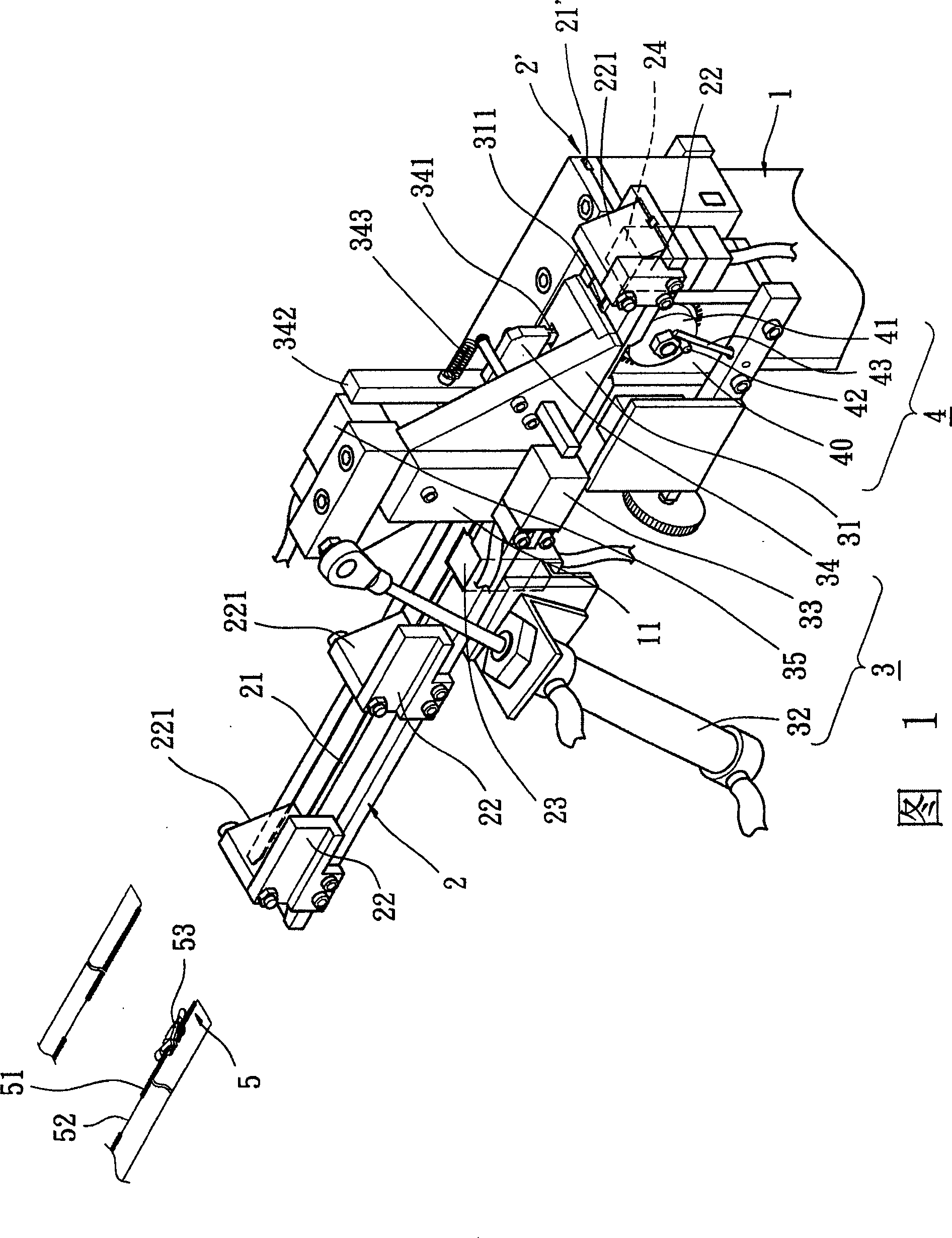
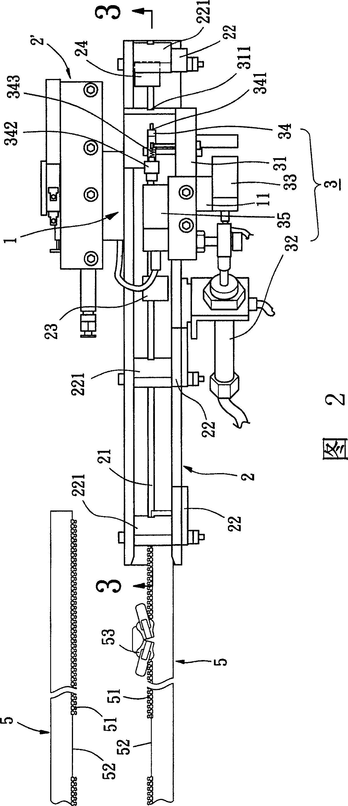
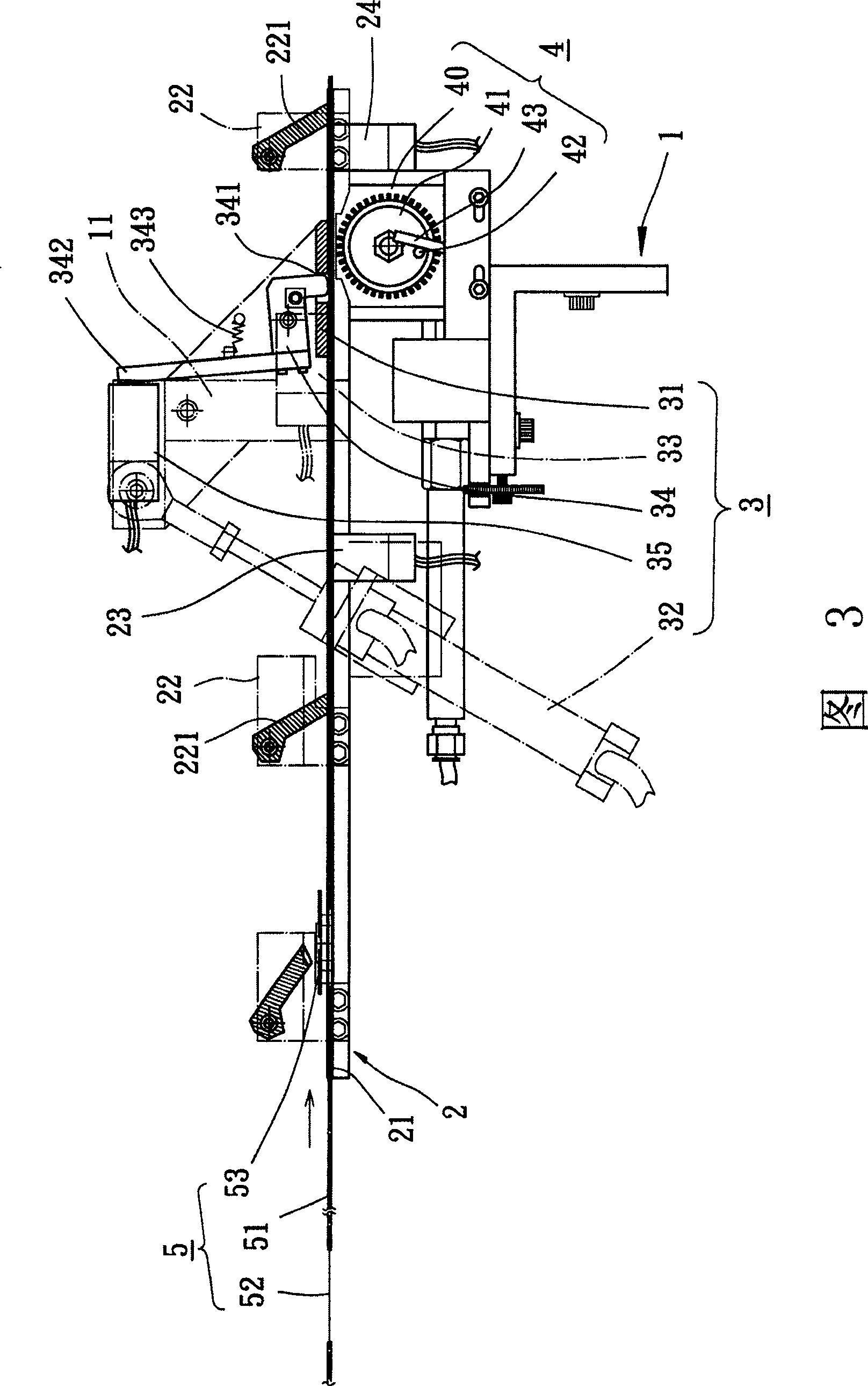
[0019] As shown in Figures 1 and 2, the injection positioning structure of the zipper with slider in the preferred embodiment of the present invention generally includes a base 1, a main seat plate 2, a primary seat plate 2', a movable plate group 3 and One count gear set 4. The base 1 can be arranged in parallel with the main seat plate 2 and the secondary seat plate 2', and the base 1 is provided with a pivot seat 11 for pivoting the movable plate group 3, and the counting gear set 4 is It is located below the main seat plate 2. The injection positioning structure of the present invention can be assembled in front of a combination mold (not shown), and the injection positioning structure is used to pre-...


PUM


Abstract

The invention discloses a jetting location construction of zip with slider, which is characterized by the following: comprising a principal saddle, a active plate and a counting cluster gear; arranging a guidance and di-slider sensing element; guiding at least one zip strip forward with the guidance; sensing one slider of the zip strip whether near or pass the active plate with the di-slider sensing element; controlling up or down of the active plate pivot; making the slider pass the active plate; arranging a hypodontia sensing element on the active plate; sensing a hypodontia sensing element of the zip strip; controlling the counting cluster gear to count the zip strip whether advance to a preset relative position; stopping the advanced movement of the zip strip; benefiting for jetting movement of several accessories for front stage zip strip with a composite die at rear.

Description

technical field [0001] The present invention relates to an injection positioning structure of a slider-attached zipper, especially about using two slider sensing parts and a drive cylinder to control and drive a movable plate to pivot up or down so that a zipper cloth strip The slider passes through a feeding and shooting mechanism to improve the positioning accuracy of the zipper before shooting. Background technique [0002] The commonly used injection positioning structure for zippers is as described in the Taiwan Patent Announcement No. 208889 "Feeding Injection Structure for Zipper Opening" that was previously applied by the applicant. A feeding positioning mechanism is arranged in front of a combination mold. The feeding positioning mechanism is provided with an upper seat plate, a lower seat plate and a gear seat on a base, and the upper seat plate is provided with a side groove for threading and pulling a zipper cloth strip. The lower seat plate is provided with a s...

Claims


Application Information

Patent Timeline
Patent Type & Authority Patents(China)
IPC IPC(8): A44B19/42
Inventor 郑荣元
Owner UNITECH ZIPPER & MACHINERY
Learn More