Rotation type damping device with variable specific travel

A damping device and rotating technology, applied in elastic resistance devices, sports accessories, muscle training equipment, etc., can solve the problems of bulky, high cost, and loud noise

Inactive Publication Date: 2009-06-10
OCEAN UNIV OF CHINA
View PDF6 Cites 0 Cited by
  • Summary
  • Abstract
  • Description
  • Claims
  • Application Information

AI Technical Summary

Problems solved by technology

[0003] The purpose of the present invention is to overcome the disadvantages of the prior art such as large volume, high cost and high noise, and provide a rotary variable ratio stroke damping device, so that several large fitness and training equipment can be miniaturized and familyized, and more fitness equipment can be used. Devices enter the family room and contribute to people's health

Method used


Image

  • Rotation type damping device with variable specific travel
  • Rotation type damping device with variable specific travel

Examples


Embodiment Construction

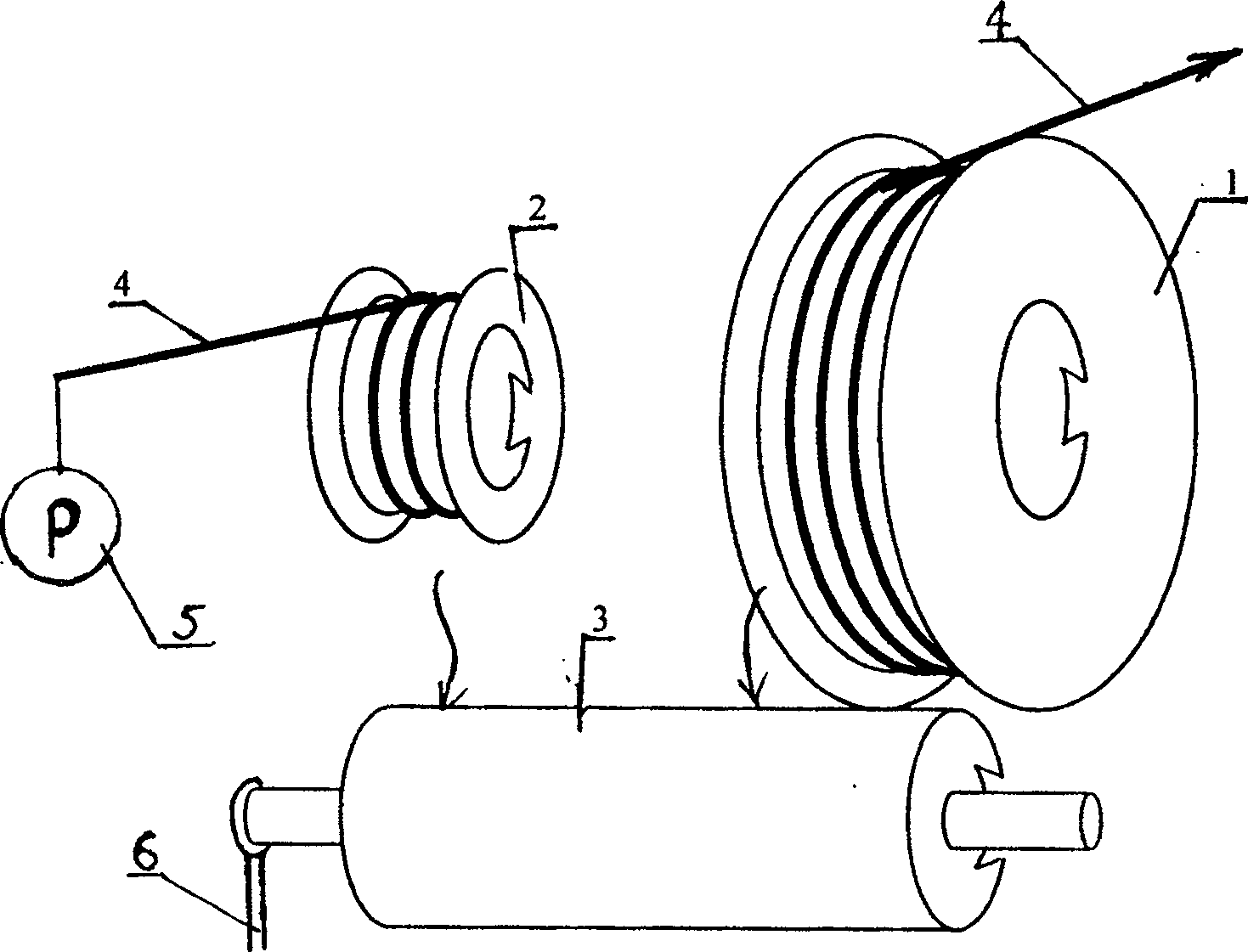
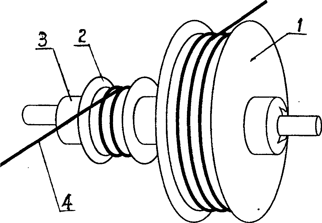
[0010] The present invention includes a transmission device and a resistance source 5, which is characterized in that the transmission device is composed of a fixed shaft 3, a bracket 6, a large transmission wheel 1 and a small transmission wheel 2 wound with a steel cable 4, and the large transmission wheel 1 and the small transmission wheel 2 All are arranged on the fixed shaft 3, the thin-diameter shaft bodies at both ends of the fixed shaft 3 are arranged on the bracket 6, the output end of the steel cable 4 on the large transmission wheel 1 is connected with the exerciser's limbs, and the steel cable 4 of the small transmission wheel 2 The resistance source 5 that output end is connected, the inner end of steel cable 4 is all fixed on the outer diameter edge of large and small transmission wheels 1,2, and the outer end (output end) of large transmission wheel 1 links to each other with exerciser's motion limb (as figure 1 indicated by the arrow in). Such as figure 1 The ...


PUM


Abstract

A rotational ratio-stroke damper for setting-up apparatus is composed of trasmission unit and resistance source. Said transmission unit has a fixing shaft supported by the supporting frame has a big and a small transmission wheels wound by steel cable and with the transmission ratio of (1.1-20):1. The output end of the steel cable wound on the small wheel is connected to resistance source. Its advantages are small size and no need of counterweight.

Description

technical field [0001] The invention relates to a rotary-type variable-ratio stroke damping device in a sports body-building apparatus. Background technique [0002] The damping device is composed of a resistance source and a damping transmission device. It is a key component of fitness equipment and training equipment. There are large-scale strength training equipment and fitness equipment. The long linear distance can reach about two meters. This is because the metal counterweight as the resistance source is not only bulky and inconvenient, but also noisy, and the damping device or system composed of it needs to be equipped with a damping guide bar and a vertical frame of more than two meters. Therefore, it is difficult to enter high-rise buildings or common families with regard to space and cost. Contents of the invention [0003] The purpose of the present invention is to overcome the disadvantages of the prior art such as large volume, high cost and high noise, and p...

Claims


Application Information

Patent Timeline
Patent Type & Authority Patents(China)
IPC IPC(8): A63B21/008A63B21/02A63B21/00
Inventor 洪涛洪雁
Owner OCEAN UNIV OF CHINA
Why Eureka
Try Eureka