Electroacoustic transducer comprising a membrane with an improved pleats area

An electroacoustic transducer and diaphragm technology, applied in the direction of diaphragm structure, speaker diaphragm shape, non-planar diaphragm/paper cone, etc., can solve problems such as diaphragm interference, insufficient sound reproduction, uneven installation state, etc. , to achieve the effect of loud sound reproduction and simple structure

Inactive Publication Date: 2009-06-10
KNOWLES ELECTRONICS ASIA
View PDF4 Cites 0 Cited by
  • Summary
  • Abstract
  • Description
  • Claims
  • Application Information

AI Technical Summary

Problems solved by technology

With this known converter, there is unfortunately the problem of interfering influences on the diaphragm, which may be due, for example, to the fact that uneven mounting conditions occur when the diaphragm is mounted to the converter housing, for example due to the adhesive caused by an uneven distribution, which can lead to unwanted vibrations within the diaphragm at a certain frequency, with the result that the vibrating part of the diaphragm used to generate sound no longer vibrates parallel to the diaphragm axis precisely enough, but causes a An undesirable destructive movement that usually involves torsional movement about an axis of rotation that is transverse and sometimes even completely perpendicular to the axis of the transducer, with the result that the oscillating coil attached to the diaphragm does not move precisely parallel to the axis of the diaphragm desired movement of the oscillating coil, but a movement deviating from this desired movement, which may have the result that the oscillating coil undesirably strikes parts of the known transducer magnet system immediately adjacent to the oscillating coil
In the known converter, the generation of such undesired destructive movements can be prevented by feeding less electrical energy to the oscillating coil, but this has the disadvantage that the acoustic energy available with the converter can only be Relatively low, so in many applications (such as in so-called speakerphones) only relatively low insufficient sound reproduction can be obtained

Method used


Image

  • Electroacoustic transducer comprising a membrane with an improved pleats area
  • Electroacoustic transducer comprising a membrane with an improved pleats area
  • Electroacoustic transducer comprising a membrane with an improved pleats area

Examples


Embodiment Construction

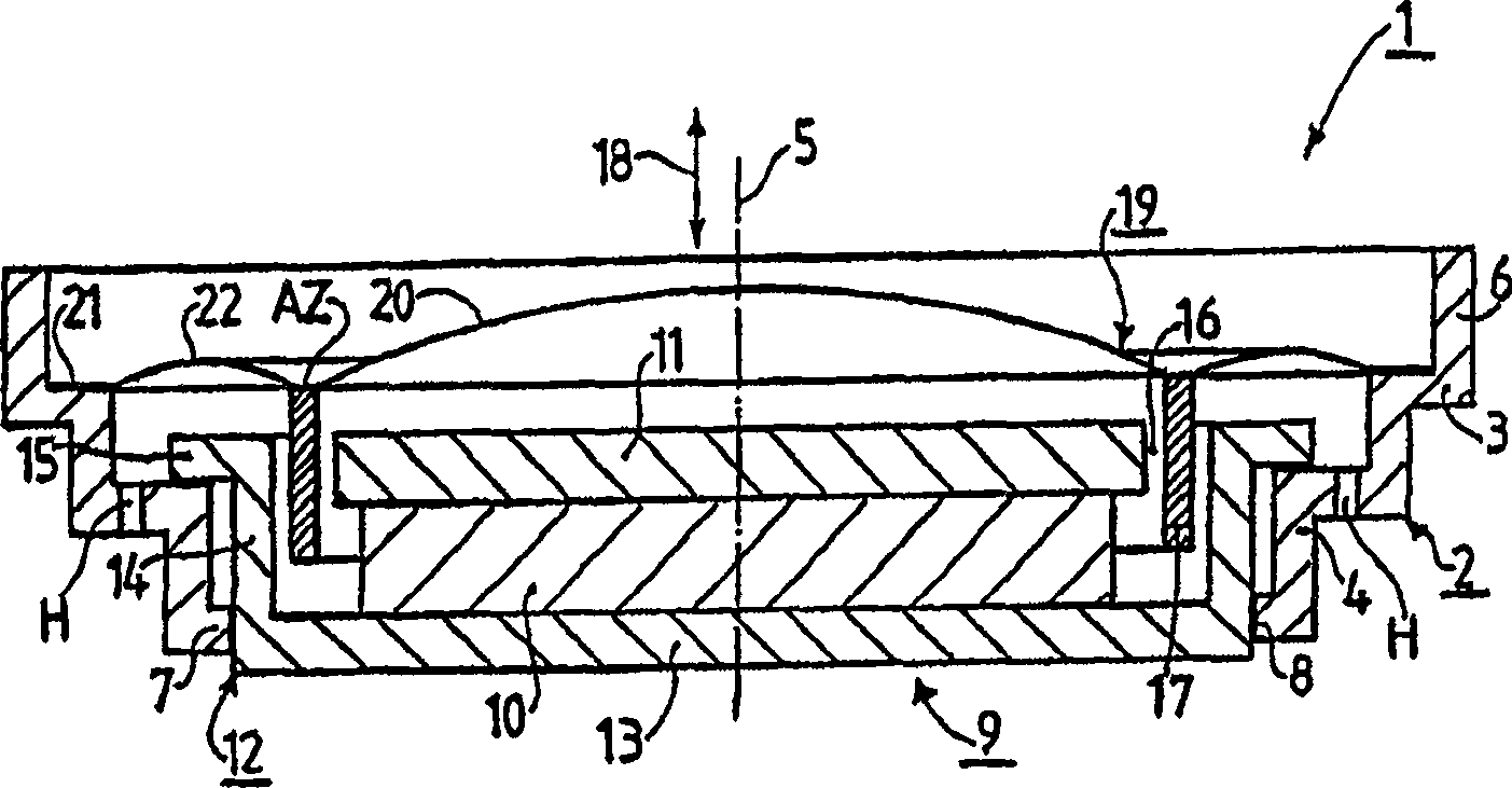
[0021] figure 1 Denotes an electro-acoustic transducer 1, hereinafter referred to as transducer 1 for the sake of brevity and embodied as a loudspeaker. The converter 1 has a plastic housing 2 comprising a first bend 3 and a second bend 4, and the two bends 3 and 4 meet each other. A plurality of holes H are provided in the area of ​​the second bend 4 in order to communicate the so-called rear space with the auditory free space. The first bend 3 is connected to a hollow cylindrical part 6 of the housing extending in the direction of the converter axis 5 . Whereas the second bend 4 is connected to the housing flat part 7 in which a cylindrical opening 8 is provided.

[0022] The converter 1 has a magnet system 9 . The magnet system 9 comprises a magnet 10 , a pole plate 11 and a case 12 which is generally called an outer case and comprises a case base 13 , a hollow cylindrical case part 14 and a case ferrule 15 projecting radially from the case part 14 . The entire magnet s...


PUM


Abstract

An electroacoustic transducer (1) has a diaphragm (19), the diaphragm (19) has a diaphragm axis (5) and an annular pleated area (22), and the pleated area (22) is provided with a plurality of pleats ( 26, 27, 28, 32, 33, 34, 38, 39, 40), and the diametrically opposite pleats include at least one different pleat parameter, characterized in that the annular pleat zone (22) is divided into a plurality of rings Segments (23, 24, 25), wherein the pleats (26, 27, 28) in the center of the ring segment (23, 24, 25) stretch straight along the radial direction (29, 30, 31), and in the ring segment (23 , 24, 25) all other pleats (32, 33, 34) are parallel to the pleats (26, 27 , 28) Stretch.

Description

technical field [0001] The invention relates to an electroacoustic transducer with a diaphragm having a diaphragm axis and an annular pleated region in which a plurality of pleats is provided. [0002] The invention also relates to a membrane for an electroacoustic transducer, which membrane has a plurality of pleat-shaped annular pleat regions in which the membrane axis is arranged. Background technique [0003] An electro-acoustic transducer corresponding to the embodiment described in the first paragraph and a membrane corresponding to the embodiment described in the second paragraph are known, for example, from US patent 6,308,327A. In the solution known from the above-referenced patent, the plurality of pleats provided in the pleat zone have the same structure throughout the pleat zone, ie the same mechanical structural state always occurs successively. In other words, this means that all pleats agree with each other in terms of pleat parameters, thus having the same p...

Claims


Application Information

Patent Timeline
Patent Type & Authority Patents(China)
IPC IPC(8): H04R7/20H04R7/18H04R7/14
CPCH04R7/20H04R2307/207
Inventor E·弗拉斯尔
Owner KNOWLES ELECTRONICS ASIA
Why Eureka
Try Eureka