Liquid dispenser for liquid container

A liquid dispenser, container technology, applied in liquid/fluid solids measurement, dispensing device, volume measurement and fluid delivery, etc., can solve the problems of high viscosity of bath or hand sanitizer, difficult operation for children and the elderly, etc.

Inactive Publication Date: 2009-07-01
小林泰
View PDF5 Cites 3 Cited by
  • Summary
  • Abstract
  • Description
  • Claims
  • Application Information

AI Technical Summary

Problems solved by technology

In addition, due to the high viscosity of the shampoo, body wash or hand soap contained in the container, considerable force must be applied to depress the operating hammer and the operating piece
Children and the elderly are not easy to operate this liquid dispenser

Method used


Image

  • Liquid dispenser for liquid container
  • Liquid dispenser for liquid container
  • Liquid dispenser for liquid container

Examples


Embodiment Construction

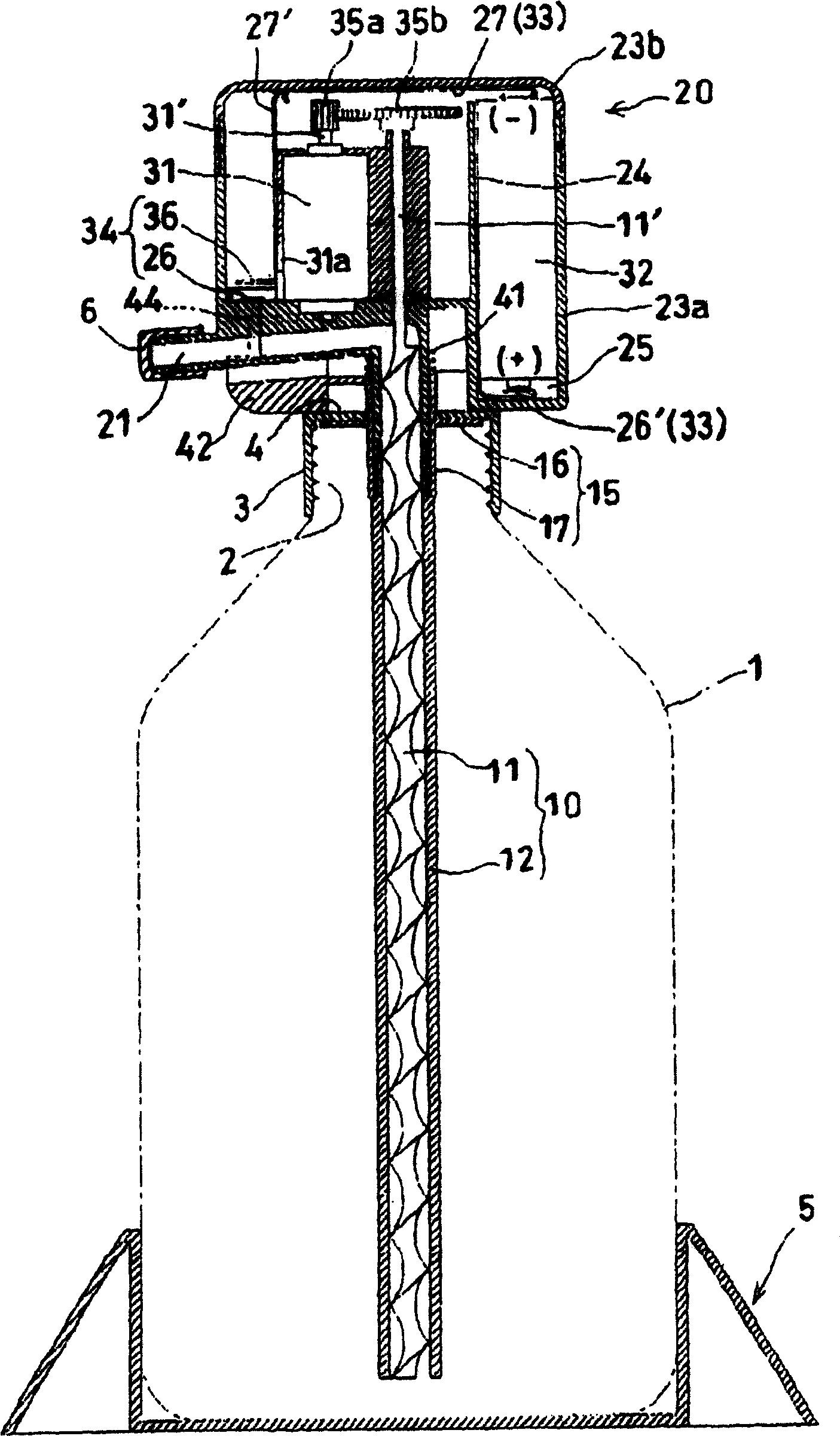
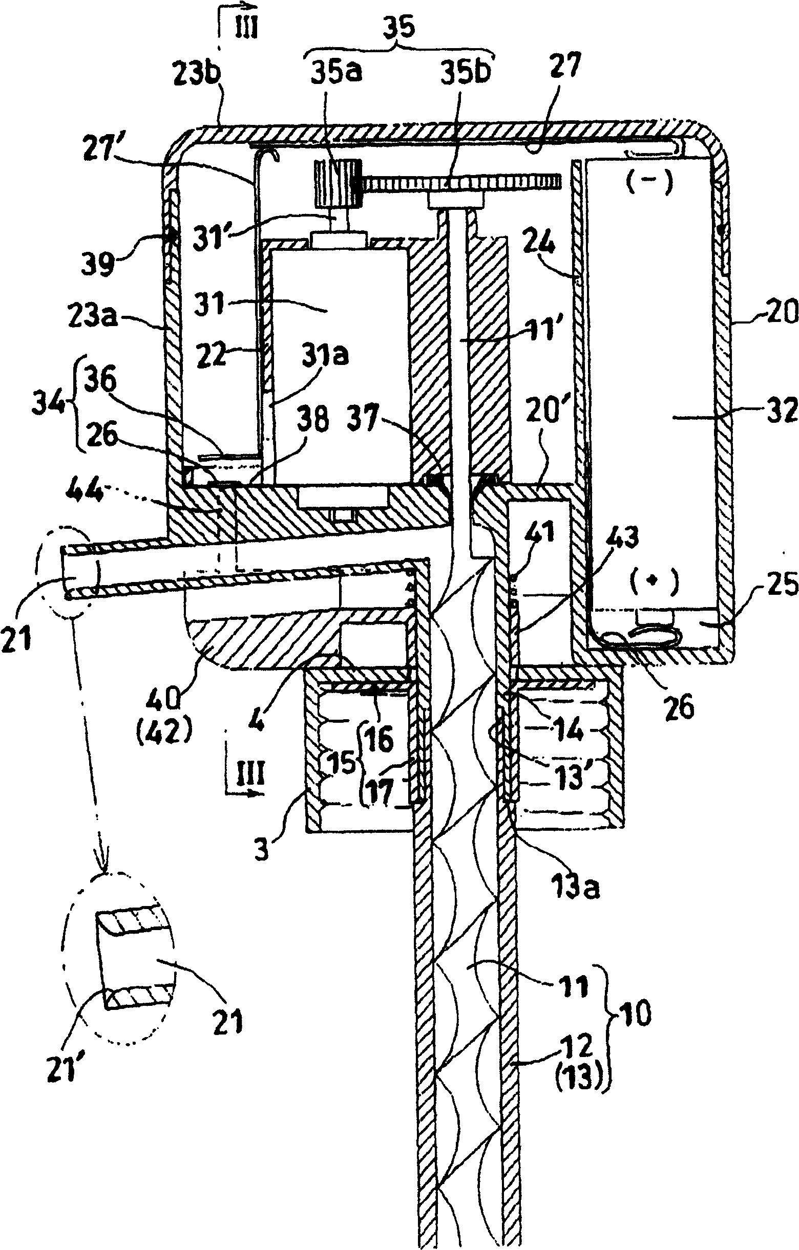
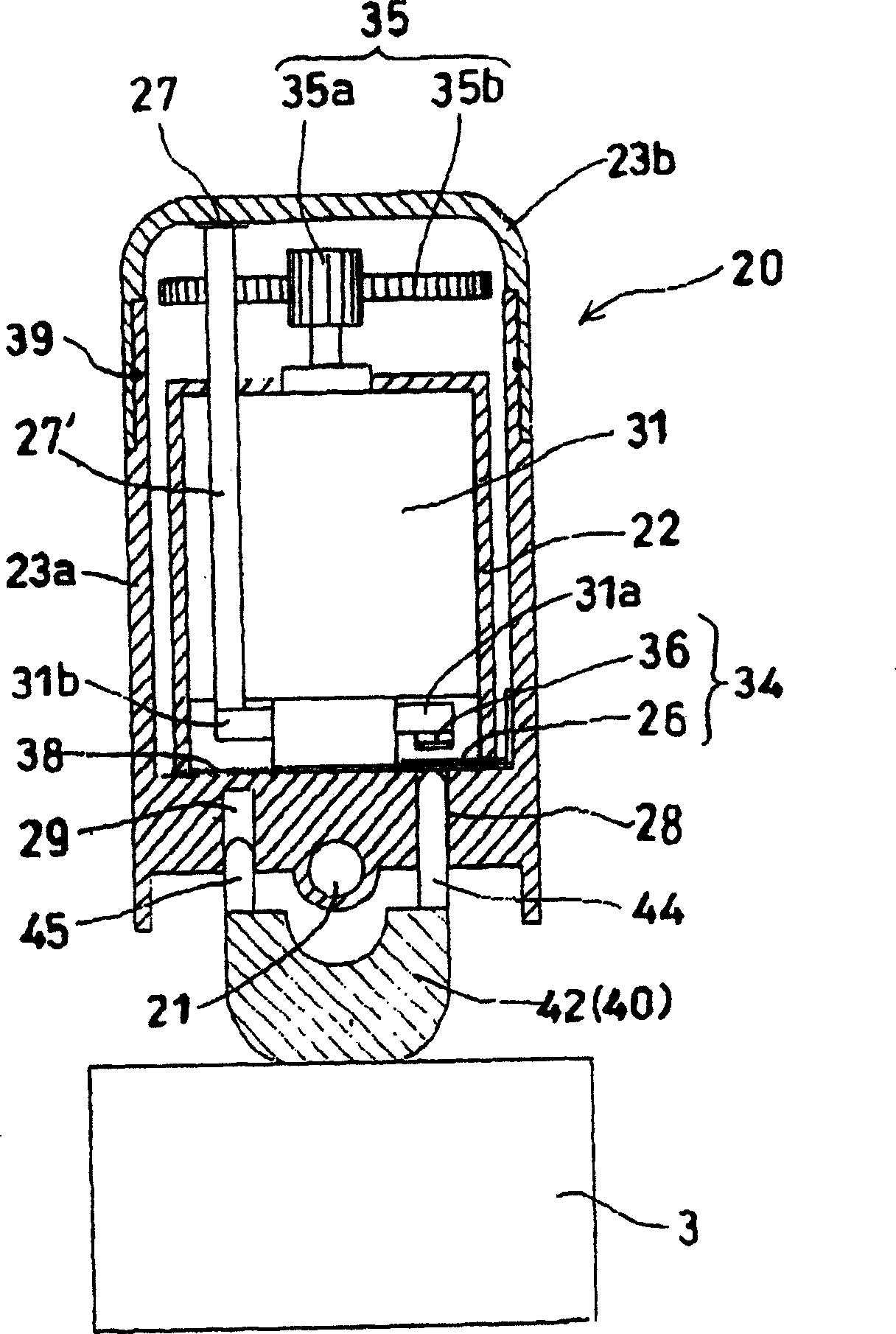
[0032] Hereinafter, a liquid dispenser of the present invention, which is used for a container containing liquid therein, will be described in detail with reference to the accompanying drawings.

[0033] Figure 1 to Figure 6 A liquid dispenser according to a first embodiment of the present invention is shown. In these figures, reference numeral 1 denotes a container containing a viscous liquid such as shampoo therein, and numeral 2 denotes a discharge opening of the container 1, which has external threads on its outer periphery so that a cover 3 can be formed along the The internal thread on its inner periphery is screwed onto the outlet until the cap 3 is fixed on the outlet.

[0034] The liquid lifting device identified with reference numeral 10 comprises a screw conveyor 11 and a cylindrical tube 12 surrounding the screw conveyor 11. When the cover 3 is mounted on the discharge opening 2, the screw conveyor 11 and the cylindrical tube The upper end parts of 12 protrude u...


PUM


Abstract

A liquid dispenser for a cap mounted on a discharge opening of a container containing a liquid, wherein the liquid dispenser includes a liquid lifting device and a housing, the liquid lifting device being supported on the upper wall of the cap And pass through the upper wall of the cover, and the liquid lifting device includes a screw conveyor and a cylindrical tube surrounding the screw conveyor, the screw conveyor and the cylindrical tube have an upper end portion and a lower end portion, when the cover is installed on the When the discharge port of the container is on, the upper end parts of the screw conveyor and the cylindrical pipe protrude upwards from the upper wall respectively, and the lower end parts of the two are inserted into the container, and the housing is suitable for accommodating the driving device of the screw conveyor. The drive means is used to rotate the screw conveyor in the liquid lifting device, and the housing is equipped with output nozzles to allow the liquid lifted by the liquid lifting device to flow out of the liquid distributor.

Description

technical field [0001] The present invention relates to a liquid dispenser which is installed at the outlet of a container for containing a viscous liquid, such as shampoo, body wash or hand soap, and which is used for drawing from the container Just the right amount of liquid. Background technique [0002] Liquid dispensers of this type have been known hitherto. Known liquid dispensers of this type usually erect an operating hammer from the center of a cover mounted on the discharge port of the container, and an operating member is provided at the upper end of the operating hammer. Utilizing the air pump principle, i.e. giving the operating member a push force through the palm of the user until the operating hammer is depressed, this known liquid dispenser can cause the liquid contained in the container to flow out through an output nozzle formed in the cover. . In this way, the user can use one of his palms to receive the liquid flowing out from the output nozzle, and u...

Claims


Application Information

Patent Timeline
Patent Type & Authority Patents(China)
IPC IPC(8): B65D83/76B65D47/34B65D25/38G01F11/10G01F13/00
CPCG01F13/005G01F11/10
Inventor 小林泰
Owner 小林泰
Why Eureka
Try Eureka