Dual safety lock
A double insurance and lock head technology, applied in the field of locks, can solve the problems of discrepancies, inconvenient use, difficult to recover, etc., and achieve the effect of preventing illegal opening, good safety performance, and low power consumption
- Summary
- Abstract
- Description
- Claims
- Application Information
AI Technical Summary
Problems solved by technology
Method used
Image

Examples
Embodiment 1
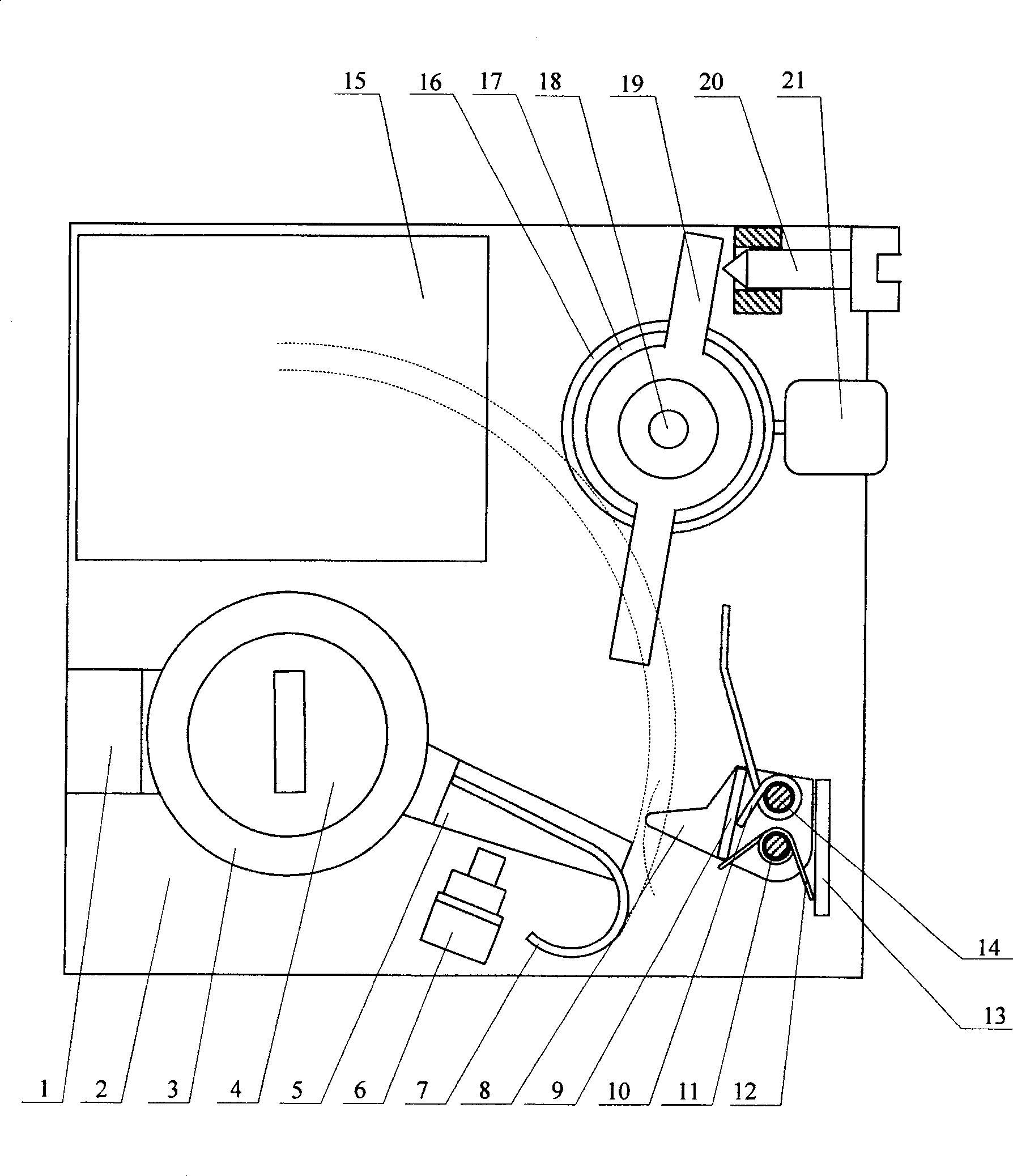
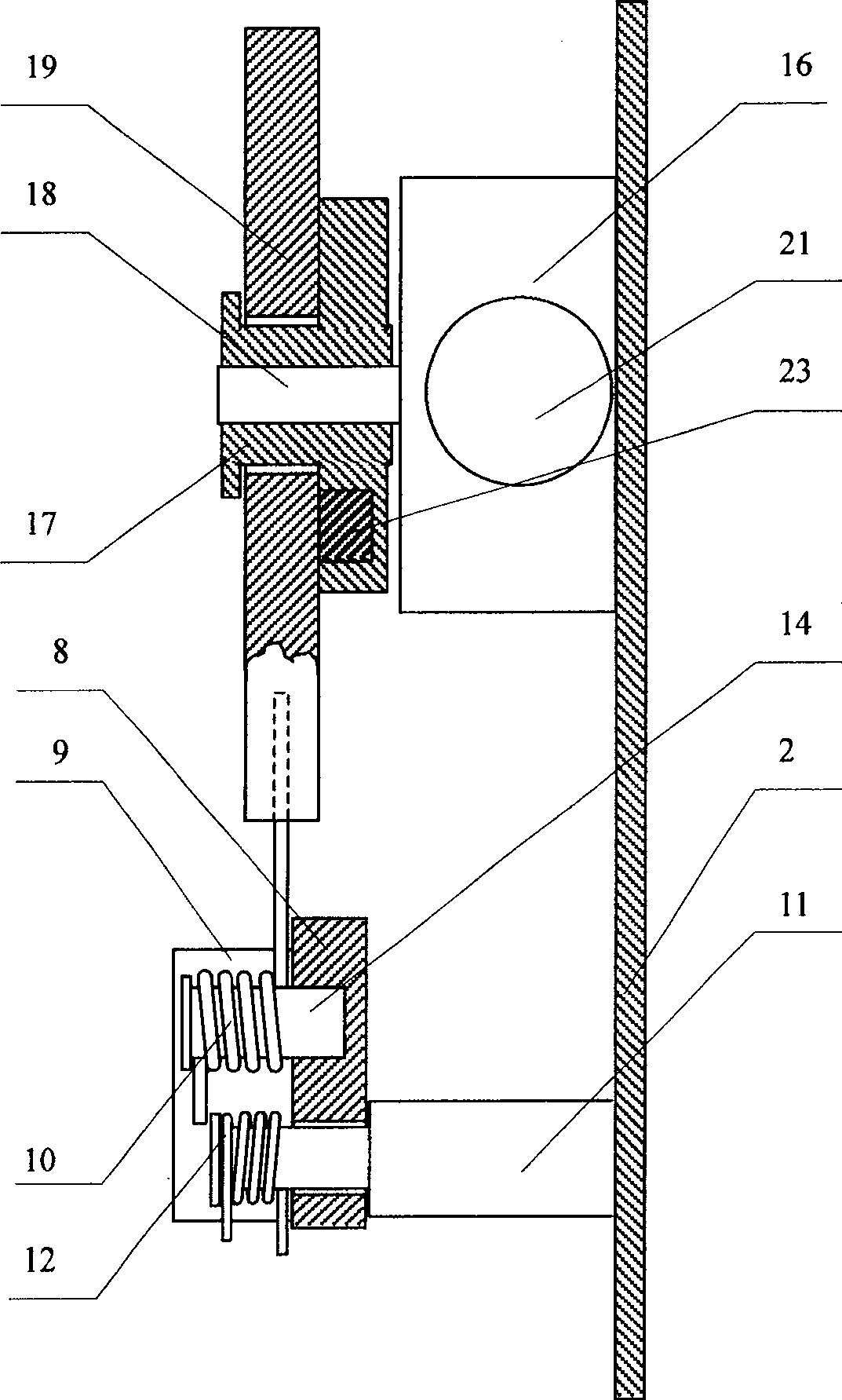
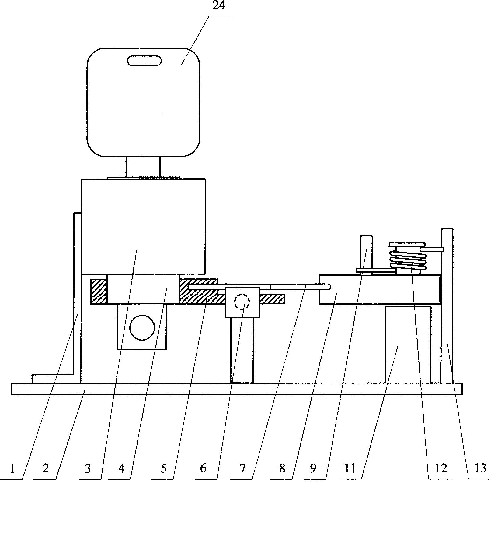
[0031] Such as figure 1 , figure 2 with image 3 As shown, the double safety lock head of the present invention mainly includes: a lock core 4 placed in the lock body 3, a crank 5 is installed at the end of the lock core 4, and an elastic driving rod 7 is installed on the crank 5; the lock body 3 is composed of The lock body support 1 links to each other with the base plate 2, and the base plate 2 is fixedly installed with a motor 21 and a reduction gear, and its input end is connected with the motor 21, and its output end is connected with the crank blocking device; the base plate 2 is also provided with a reset mechanism and A switch6.
[0032] This embodiment adopts the common connection method that the crank 5 is directly installed on the end of the lock cylinder 4; the speed reduction device is a miniature speed reducer 16; There is a magnet 23 between 17 and the ratchet rod 19, and the friction disc 17 is set on the output shaft of the miniature reducer 16; the struc...
Embodiment 2
[0041] Such as Figure 10 with Figure 11 As shown, the present embodiment adopts the common connection method that the crank 5 is directly mounted on the end of the lock cylinder 4; The worm gears 22 mesh with each other, and the worm screw 28 is sleeved on the motor shaft. At this time, the worm wheel 22 can also serve as the output end of the reduction gear and the friction disc. The crank blocking device is a ratchet bar 19 with a friction transmission mechanism. In this embodiment, an elbow is added on the ratchet bar 19. The structure of its friction transmission mechanism is: a stage clip 25, a lock nut 26 and a compression spring are arranged on the worm wheel 27. The ring 33, the locking nut 26 and the clip spring 25 press the ratchet bar 19 on the surface of the worm wheel 22 through the clip ring 33 to form a friction pair. Both arms of the shift fork 8 are rigid arms.
[0042] The working principle and unlocking process of the above-mentioned structure are the ...
Embodiment 3
[0044] Such as Figure 12 with Figure 13 As shown, the crank 5 of this embodiment is installed on other transmission parts connected with the lock cylinder 4. The specific structure is: the crank gear shaft 29 is fixedly installed on the bottom plate 2, the crank 5 is fixedly installed on the gear 30, and is set on the crank gear together. The shaft 29 has a lock cylinder gear 32 on the lock cylinder 4, and the lock cylinder gear 32 meshes with the crank gear 30 to transmit the rotation of the crank 5 by the key 24. The reduction gear is the same as in Embodiment 2. The crank blocking device is a ratchet bar 19 with a friction drive mechanism, and the elbow bar 19 also has an elbow as in embodiment 2, and the structure of its friction drive mechanism is the same as in embodiment 1. The structure of its reset mechanism is the same as that of Embodiment 1, except that the shift fork 8 uses the elastic piece 37 as the active arm.
[0045] The working principle of the above st...
PUM
 Abstract
Description
Claims
Application Information
 - R&D Engineer
- R&D Manager
- IP Professional
- Industry Leading Data Capabilities
- Powerful AI technology
- Patent DNA Extraction
Browse by: Latest US Patents, China's latest patents, Technical Efficacy Thesaurus, Application Domain, Technology Topic.
© 2024 PatSnap. All rights reserved.Legal|Privacy policy|Modern Slavery Act Transparency Statement|Sitemap