Lock catch device of vehicle sliding groove and method of manufacturing the same

The invention relates to a locking device and a manufacturing method, which are applied in the field of automobile chute locking devices, and can solve the problems of failure of the automobile sliding slot locking device, troublesome stopping, matching errors, etc., so as to improve the product qualification rate and production efficiency, and improve the Safety, Overcoming Failure Effectiveness

Active Publication Date: 2009-08-05
苏州红荔汽车零部件有限公司
View PDF5 Cites 0 Cited by
  • Summary
  • Abstract
  • Description
  • Claims
  • Application Information

AI Technical Summary

Problems solved by technology

Yet the existing car chute locking device has the following defects: 1. The car chute locking device is often set separately from the sliding core. When working, it directly acts on the sliding core as a stopper to limit its sliding. The relative movement between the core and the car chute lock device often leads to a matching error between the two, which brings trouble to the stop; 2. There is often only one braking structure on the car chute lock device, which is usually connected to the artificial seat of the seat. On the handle, if the car chute locking device is to be braked from another angle through other mechanisms, such as an electric stretching mechanism, it is obviously necessary to refit the existing car chute locking device, which is extremely cumbersome; And once the braking structure fails, the automobile chute locking device will also fail

Method used


Image

  • Lock catch device of vehicle sliding groove and method of manufacturing the same
  • Lock catch device of vehicle sliding groove and method of manufacturing the same
  • Lock catch device of vehicle sliding groove and method of manufacturing the same

Examples


Embodiment

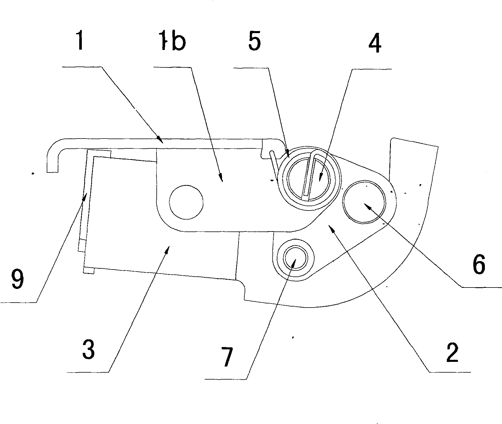
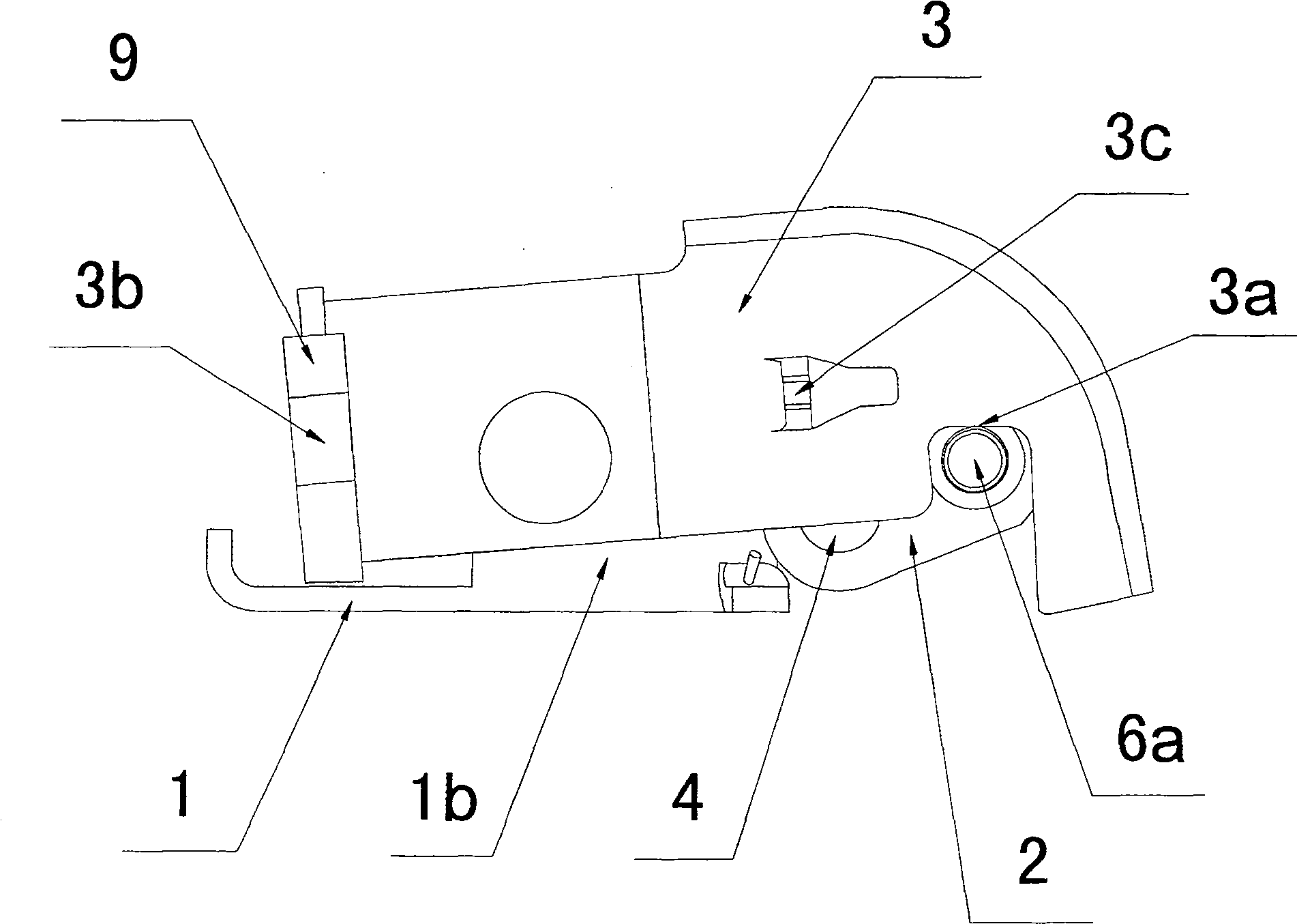
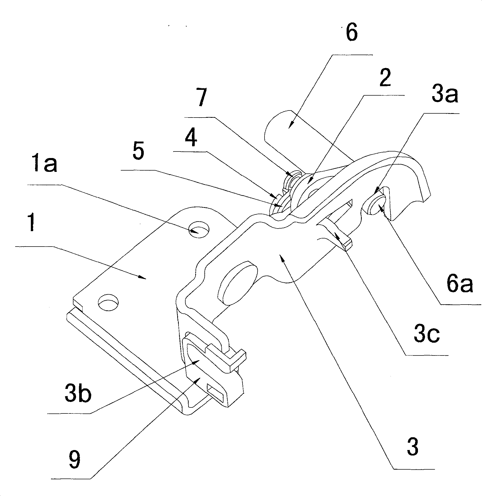
[0026] Example: such as figure 1 , figure 2 , image 3 Shown is the specific embodiment of the automobile chute locking device of the present invention, which includes a base frame 1, a rotating piece 2 and a trigger frame 3; a number of fixing holes 1a are opened on the body of the base frame 1, and a joint connected to the body is formed. The folded part 1b and the rotating piece 2 are riveted below the folded part 1b by a split rivet 4. The split rivet 4 is covered with a torsion spring 5; 1b is movable and riveted, that is, it cannot rotate with the rotating piece 2; and one end of the torsion spring 5 is fixed on the base frame 1, and the other end is inserted into the bayonet of the split rivet 4.

[0027] The rotating piece 2 is also fixedly riveted with a long shaft 6 and a rivet 7, and the riveted part 6a of the long shaft 6 protrudes from the rotating piece 2; The buckle groove 3a, the riveting portion 6a of the long axis 6 abuts into the buckle groove 3a.

[00...


PUM


Abstract

The invention discloses an automobile chute locking device, which comprises a base frame, a rotating piece and a trigger frame; it is characterized in that a number of fixing holes are opened on the body of the base frame, and a folded part connected with the body is formed, and the rotating piece is connected by An open rivet is movably riveted under the folding part, and the open rivet is covered with a torsion spring; the rotating piece is fixedly riveted with a long axis and a zipper rivet, and the riveted part of the long axis protrudes from the rotating piece; the trigger frame is also movably riveted on the aforementioned folding part On the trigger frame, there is a buckle groove, and the riveted part of the aforementioned long axis is pressed into the buckle groove. It is directly fixed on the sliding core and moves synchronously with the sliding core, and cooperates with the stopper in the chute to stop the sliding core, so there is no coordination error between the sliding core and the sliding core can be stopped conveniently and quickly at any time. And it has two braking mechanisms, which improves the practicability of this type of automobile chute locking device, and also overcomes the shortcoming that the failure of one braking structure leads to the failure of the entire automobile chute locking device.

Description

technical field [0001] The invention relates to a locking device and a manufacturing method thereof, in particular to a car chute locking device installed in a slidable car seat chute and a manufacturing method thereof. Background technique [0002] At present, the slidable seat on the car is mainly to fix the seat support frame on the sliding core in a certain way, and the sliding core is slidably combined in the chute on the bottom surface of the carriage, and the sliding core slides in the chute to drive the seat. The chair moves together; the chute generally has a car chute lock device, its function is to limit the sliding of the sliding core in the chute, thereby stopping the seat; and itself is connected to the seat by a certain structural configuration. On the control handle (such as seat handle) that can be reached, and brake by it. Yet the existing car chute locking device has the following defects: 1. The car chute locking device is often set separately from the s...

Claims


Application Information

Patent Timeline
Patent Type & Authority Patents(China)
IPC IPC(8): B60N2/08
Inventor 胡文泰
Owner 苏州红荔汽车零部件有限公司
Why Eureka
Try Eureka