Degenerate birdcage coil and transmit/receive apparatus and method for same

A magnetic resonance imaging and coil technology, applied in magnetic resonance measurement and other directions, can solve the problem that the coil unit is not used to cover the anatomical area, and achieve the effect of improving the efficiency of the coil and improving the insulation.

Inactive Publication Date: 2009-08-12
KONINKLIJKE PHILIPS ELECTRONICS NV
View PDF8 Cites 2 Cited by
  • Summary
  • Abstract
  • Description
  • Claims
  • Application Information

AI Technical Summary

Problems solved by technology

However, unlike phased array coils, the coil units

Method used


Image

  • Degenerate birdcage coil and transmit/receive apparatus and method for same
  • Degenerate birdcage coil and transmit/receive apparatus and method for same
  • Degenerate birdcage coil and transmit/receive apparatus and method for same

Examples


Embodiment Construction

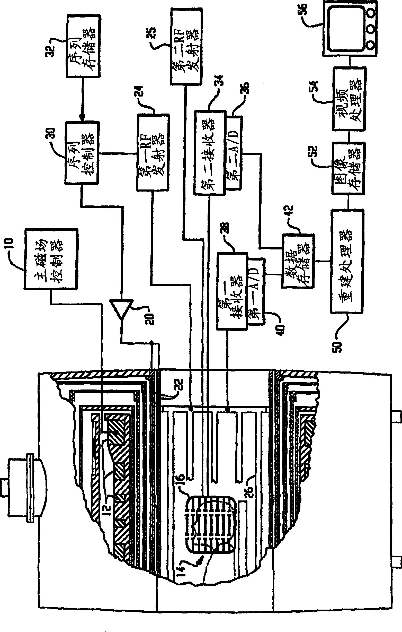
[0042] see figure 1 , describes an MRI scanner. A main field controller 10 controls a main field magnet 12, such as a superconducting or resistive magnet. The main magnet 12 is controlled to generate a substantially uniform and stable main magnetic field region B 0 , in the examination zone or region 14 the main magnetic field region B 0 with the expected strength, e.g. |B 0 | = 3.0 Tesla where the inspected is placed in the inspection area. As shown, the inspection zone 14 has a cylindrical inner diameter, but other shapes such as an open area inspection zone may also be used. Typically, B 0 It is set in the direction of the Z axis, which is the longitudinal center axis of the examination area 14 .

[0043] Pulse sequences are stored in sequence memory 32 and executed by sequence controller 30 . A sequence controller 30 controls the gradient pulse amplifier 20 and controls the first and second RF transmitters 24, 25 as required. More specifically, sequence controller...


PUM


Abstract

A birdcage coil (16) used in conjunction with a magnetic resonance imaging device includes a first conductive loop (81, 581), a second conductive loop (82, 582), and a plurality of conductive loops located between the first and second conductive loops A first conductor bar (80, 580). The third conductor (83, 83", 583) is coupled at the resonant frequency to the second conductive loop, for example via a second conductor bar (84, 84", 584). The birdcage coil also includes a switch (590) for switching the birdcage coil in at least the following modes: 1) RF transmit mode, as an RF transmit coil; and 2) RF receive mode, as an RF receive coil.

Description

technical field [0001] The present invention relates to Magnetic Resonance Imaging (MRI) techniques. The technique is particularly suitable for use in conjunction with a bore MRI scanner and will be described with particular reference to a bore MRI scanner. However, it should be understood that the invention may also be used in other similar applications and with other types of MRI scanners. Background technique [0002] Typically, in MRI, a substantially uniform, time-constant main magnetic field B 0 An examination region is established in which the object to be imaged is placed. Through magnetic resonance radiofrequency excitation and manipulation, selected magnetic dipoles in the subject are tilted (via RF pulses) into a plane transverse to the main magnetic field region, allowing them to precess and resonate without being affected by magnetic resonance Under RF excitation and operation, these magnetic dipoles are aligned with the main magnetic field. The resonant dip...

Claims


Application Information

Patent Timeline
IPC IPC(8): G01R33/36
Inventor T·奇米勒韦斯基J·A·弗洛克T·埃干
Owner KONINKLIJKE PHILIPS ELECTRONICS NV
Why Eureka
Try Eureka