Non-planar gradient coil

A gradient coil, non-planar technology, used in the measurement of magnetic variables, measuring devices, instruments, etc., to achieve the effects of improving thermal stability, improving imaging speed, and improving image quality

Pending Publication Date: 2019-04-30
RAY PLUS MEDICAL TECH CO LTD
View PDF0 Cites 4 Cited by
  • Summary
  • Abstract
  • Description
  • Claims
  • Application Information

AI Technical Summary

Problems solved by technology

[0006] In view of this, the present invention proposes a kind of non-planar gradient coil, aims at solving existing problem

Method used


Image

  • Non-planar gradient coil
  • Non-planar gradient coil
  • Non-planar gradient coil

Examples


Embodiment Construction

[0025] Exemplary embodiments of the present disclosure will be described in more detail below with reference to the accompanying drawings. Although exemplary embodiments of the present disclosure are shown in the drawings, it should be understood that the present disclosure may be embodied in various forms and should not be limited by the embodiments set forth herein. Rather, these embodiments are provided for more thorough understanding of the present disclosure and to fully convey the scope of the present disclosure to those skilled in the art. It should be noted that, in the case of no conflict, the embodiments of the present invention and the features in the embodiments can be combined with each other. The present invention will be described in detail below with reference to the accompanying drawings and examples.

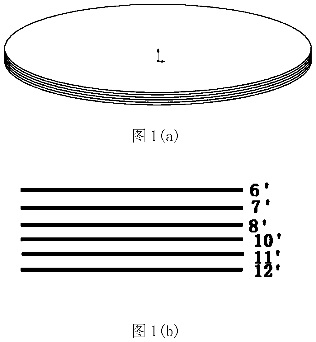
[0026] see figure 1 ,in figure 1 (a) is a three-dimensional structure diagram, figure 1 (b) is a vertical cross-sectional view. The existing gradient coil ...


PUM


Abstract

The invention provides a non-planar gradient coil. The non-planar gradient coil comprises an upper gradient coil and a lower gradient coil which are vertically symmetrical; scanning space exists between the upper gradient coil and the lower gradient coil; each of the upper gradient coil and the lower gradient coil is composed of a plurality of sub coils; the sub coils are separated by insulating layers; and in the sub coils of the upper gradient coil and the lower gradient coil, at least one sub coil is a curved coil, and the curved edge is bent towards the scanning space. Under the same condition, compared with the traditional planar gradient coil, the non-planar gradient coil has a higher gradient magnetic field intensity, smaller eddy current and less influence on the thermal stabilityof the magnet.

Description

technical field [0001] The present invention relates to the field of magnetic resonance technology, in particular to a non-planar gradient coil used in magnetic resonance imaging. Background technique [0002] Magnetic Resonance Imaging (MRI) equipment is one of the greatest inventions of the last century. It can be used to scan almost every part of the human body. It has no ionizing radiation damage to the human body, and the soft tissue structure is clearly displayed. It can be used for disease diagnosis in various parts of the body. . [0003] Gradient coil is one of the core components of MRI equipment. Its main function is to convert electrical energy into magnetic energy, which is used to generate a three-dimensional linear gradient magnetic field for magnetic resonance imaging, and to perform layer selection, phase encoding, and frequency encoding on MRI signals. The development of MRI technology puts forward higher requirements on the performance of gradient coils, ...

Claims


Application Information

Patent Timeline
IPC IPC(8): G01R33/385
CPCG01R33/385G01R33/3856
Inventor 王义槐王振任重山连建宇
Owner RAY PLUS MEDICAL TECH CO LTD
Why Eureka
Try Eureka