Backlight liquid crystal display

A liquid crystal display and liquid crystal unit technology, applied in optics, instruments, nonlinear optics, etc., can solve problems such as dark lighting and uneven illumination of the display area

Inactive Publication Date: 2009-08-12
DIEHL AKO STIFTUNG
View PDF6 Cites 1 Cited by
  • Summary
  • Abstract
  • Description
  • Claims
  • Application Information

AI Technical Summary

Problems solved by technology

However, the effect of the direct light irradiation in the opposite relation to the viewing direction causes a very uneven illumination of the display area of ​​the liquid crystal display, because a large amount

Method used


Image

  • Backlight liquid crystal display
  • Backlight liquid crystal display

Examples


Embodiment Construction

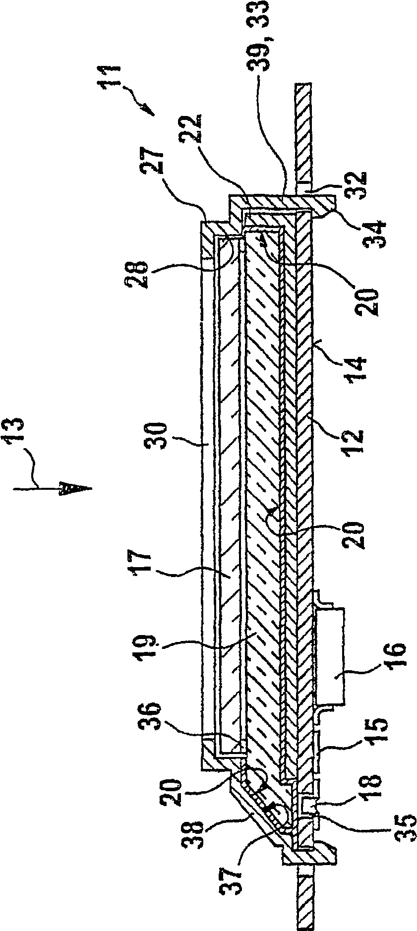
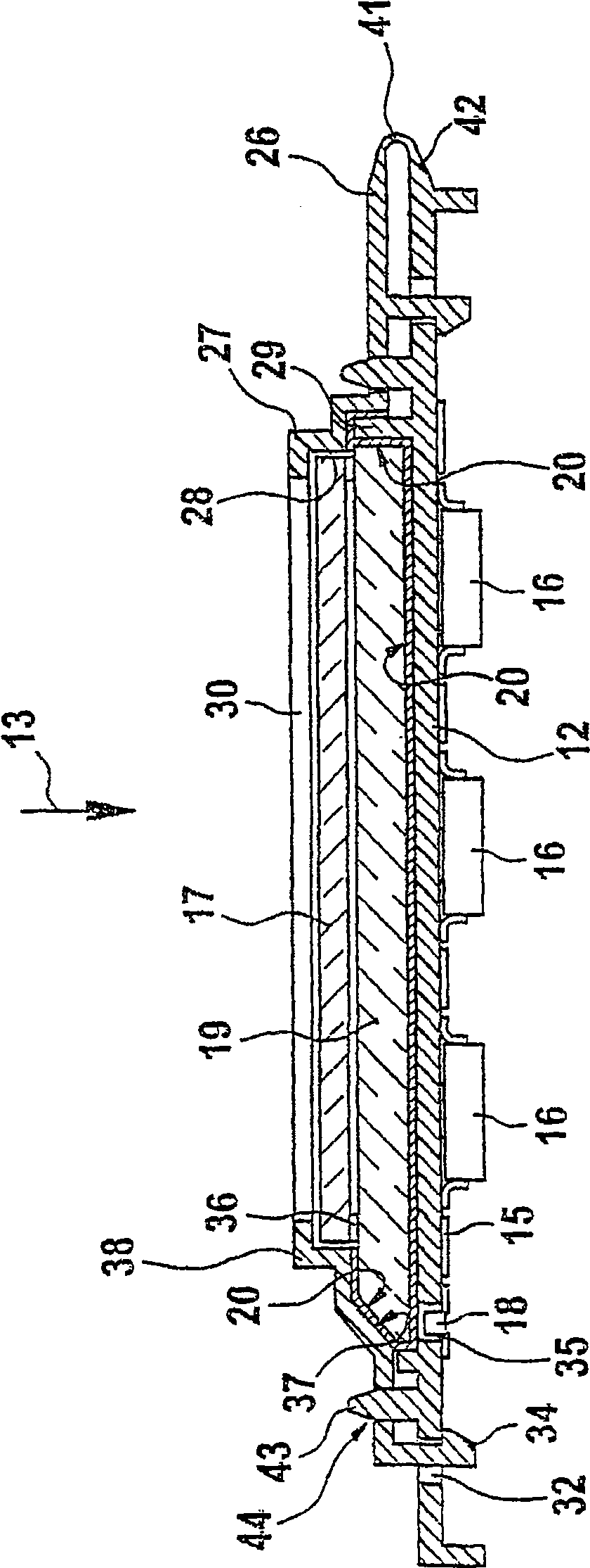
[0014] The basic structure of the sandwich structure for the display module 11 is the circuit carrier 12, such as figure 1 As shown, the liquid crystal cell 17 with its backlighting, at least on its rear side 14 away from the viewing direction 13, is provided with a printed circuit 15 for fixing and wiring of the components 16, especially for activating the liquid crystal cell 17 and the light source 18.

[0015] The light source 18 shines through the circuit carrier 12 in a direction opposite to the viewing direction 13 into an angled limb on the light guide plate 19 and is deflected at the reflector surface 37 so as to pass sideways into essentially a The light guide plate 19 is parallel to the plane. The light passes from the light guide plate, through the liquid crystal cell 17, which is arranged in front of the viewing side, perpendicular to the main plane of the light guide plate 19, again in the direction opposite to the viewing direction 13, in order to make the momen...


PUM


Abstract

The invention relates to a display module (10) with a backlit liquid crystal cell (17), in particular for use in control panels of white household appliances. If the height dimension of the module (11) is defined by means of the support of a frame (27) which fixes the liquid crystal cell (17) and the light guide plate (19) against the circuit carrier (12), the circuit carrier is provided with The surface of the light guide plate (19) in the form of a reflector surface (20) then provides a particularly inexpensive construction. The circuit carrier (12) is preferably produced using the MID technique of injection moulding, with integrated printed wiring (15) and receiving means (22) for the light guide plate (19) formed therein, said frame (27) also The frame (27) can be fitted over the sandwich structure of the light guide plate (19) and the liquid crystal cell (17) integrally pivotally connected to the circuit carrier by means of a film hinge (41). The fixation between the frame (27) and the circuit carrier (12) is achieved by means of elastic latching barb elements (34), having a slotted structure consisting of positioning studs or posts (43), which are free The ends are heat tightened to hold them in place.

Description

technical field [0001] The invention relates to a liquid crystal display. Background technique [0002] Such a display is known, for example, from JP 10-153764. In this, the liquid crystal cell is integrated in an H-shaped structure, the cross-arms of which constitute the optically active cell, and the limbs of which act as spacers between the glass plate and the circuit carrier, said glass plate being placed in the Viewing the side above, the circuit carrier is arranged below. A light guide is arranged below the optically active liquid crystal cell, which is surrounded by a reflective housing, into which light guide the light of the light-emitting diodes enters laterally. [0003] On the outside of the fingers, between the depending glass plate and the circuit carrier, there are provided rubber contacts for the electrical connection of the liquid crystal cell and the circuit carrier. This mechanical structure is completed by a box-shaped frame, which is assembled above a...

Claims


Application Information

Patent Timeline
IPC IPC(8): G02F1/13G02F1/13357D06F39/00A47L15/42D06F34/32G02F1/1335
CPCG02F2201/503A47L15/4293G02F1/133308G02F2201/465G02F1/133615D06F39/005D06F34/32
Inventor 诺伯特·莫斯奇
Owner DIEHL AKO STIFTUNG
Why Eureka
Try Eureka