
Grid drive circuit and its drive circuit unit

A gate drive circuit and circuit unit technology, applied to instruments, static indicators, etc., can solve problems such as correctness, serious thermal effects, and signal failure

Active Publication Date: 2009-08-26
AU OPTRONICS CORP
View PDF9 Cites 0 Cited by
  • Summary
  • Abstract
  • Description
  • Claims
  • Application Information

AI Technical Summary

Problems solved by technology

However, when making a large-sized liquid crystal display device, the load on the scanning lines will increase accordingly, so the driving signal will not be as correct as before due to the increased load.
In addition, the transistors in the gate drive circuit must also be relatively large to output enough drive current to drive the scan lines, but this also leads to more serious problems with thermal effects in the circuit

Method used


Image

  • Grid drive circuit and its drive circuit unit
  • Grid drive circuit and its drive circuit unit
  • Grid drive circuit and its drive circuit unit

Examples


Embodiment Construction

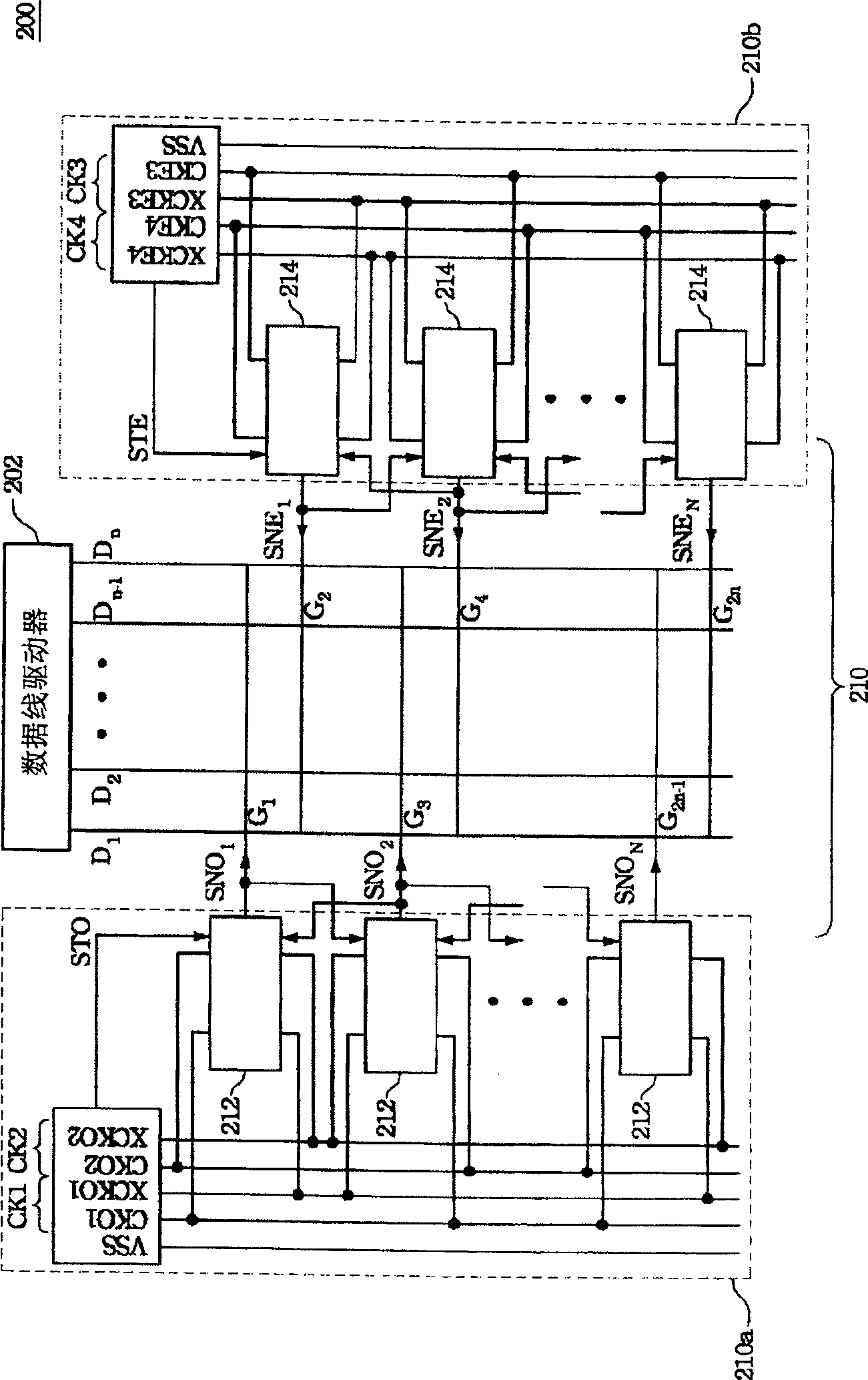
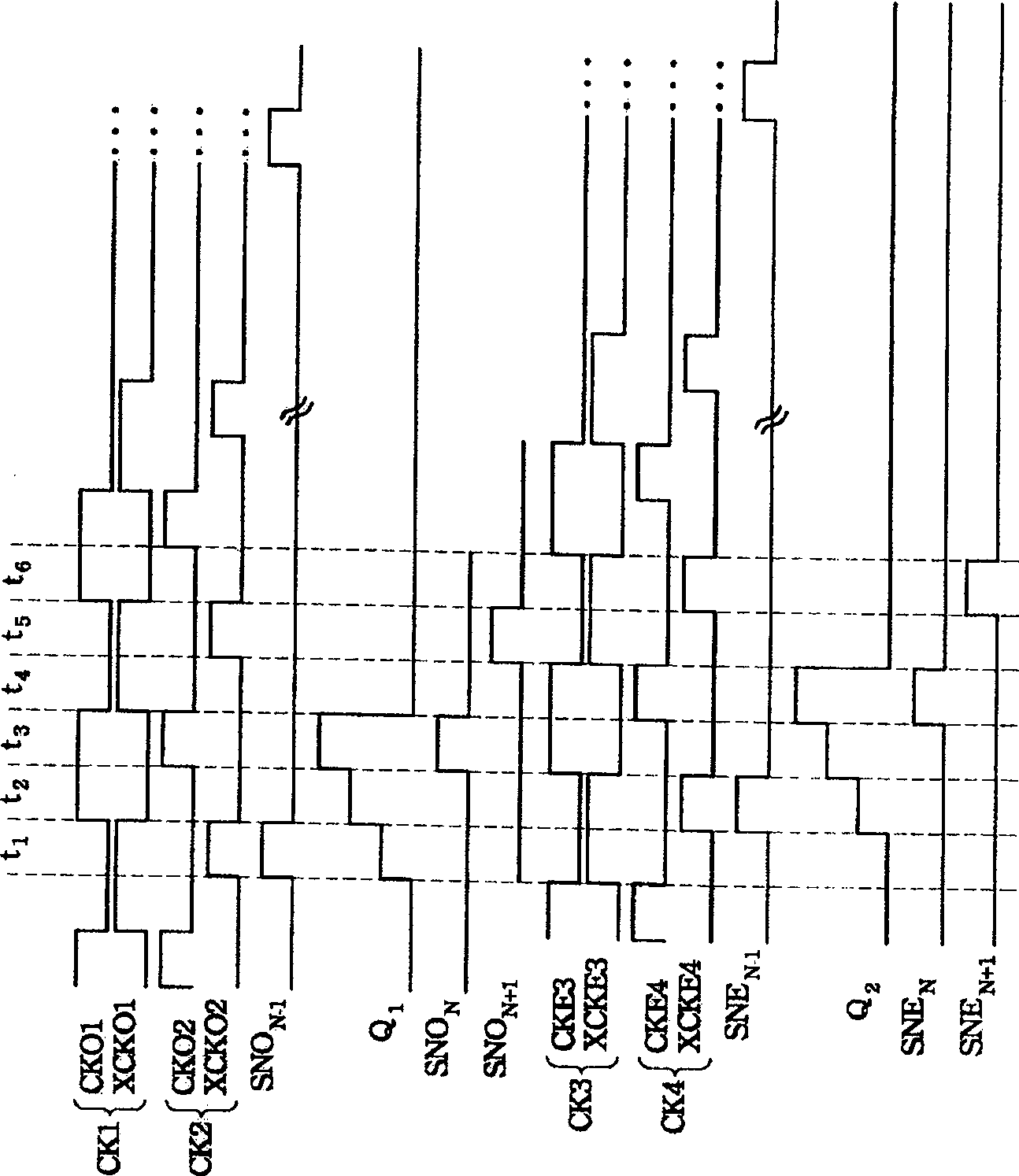
[0026] Please refer to figure 2 , shows a schematic diagram of a liquid crystal display panel according to an embodiment of the present invention. The liquid crystal display panel 200 includes a plurality of data lines D 1 …D n , multiple scanning lines G 1 …G n , a data line driver 202 and a gate drive circuit 210, wherein the gate drive circuit 210 is used to drive a plurality of scan lines G of the liquid crystal display 1 …G 2n . The gate drive circuit 210 is divided into a first gate drive circuit 210a and a second gate drive circuit 210b, wherein the first gate drive circuit 210a includes a plurality of first circuit units 212, and the second gate drive circuit 210b includes a plurality of a second circuit unit 214. The first circuit unit 212 is respectively coupled to an odd number of scan lines G 1 , G 3 ,...,G 2n-1 , and output multiple first drive signals SNO 1 …SNO N to an odd number of scan lines G 1 , G 3 ,...,G 2n-1 middle. The second circuit uni...


PUM


Abstract

The invention discloses a gate drive circuit and its drive circuit unit. The drive circuit unit is used to output a drive signal and includes an input unit, an auxiliary output unit and an output unit. The input unit is coupled to an input node and receives a start signal to make the input node have a potential. The auxiliary output unit receives a first timing signal to increase the potential of the input node. The output unit receives a second timing signal to further increase the potential of the input node, and outputs a driving signal.

Description

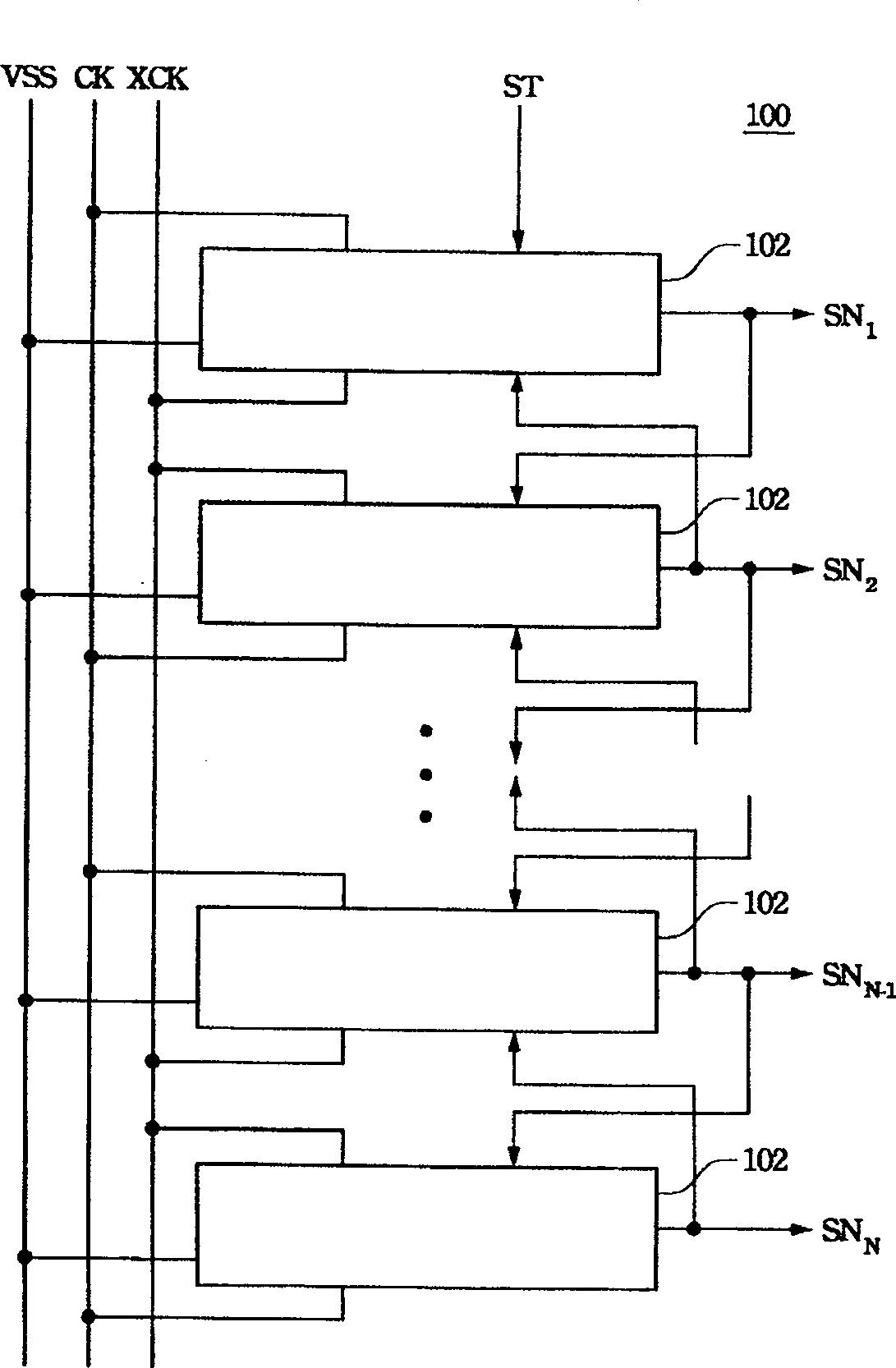
technical field [0001] The present invention relates to a gate drive circuit and its drive circuit unit, and in particular to a gate drive circuit and its drive circuit unit in a liquid crystal display device. Background technique [0002] In a general liquid crystal display device, a gate driver is usually used to output a gate driving signal to drive the scanning lines in the liquid crystal display device. However, since the cost of using the gate driver is too high, how to reduce the cost of the gate driver is very important. [0003] A known method is to fabricate a gate driving circuit on a glass substrate, and use the gate driving circuit to output gate driving signals to scan lines, thereby replacing the original gate driver and reducing manufacturing costs. Please refer to figure 1 , shows a schematic diagram of a general gate drive circuit. The gate drive circuit 100 includes a plurality of drive circuit units 102, and is controlled by a voltage source VSS and ti...

Claims


Application Information

Patent Timeline
Patent Type & Authority Patents(China)
IPC IPC(8): G09G3/36G09G3/20G02F1/133
Inventor 简志远郭育如陈婉蓉
Owner AU OPTRONICS CORP
Learn More