Supercharge Your Innovation With Domain-Expert AI Agents!

Integrated RF signal level detector usable for automatic power level control

一种射频信号、检测器的技术,应用在功率管理、增益控制、放大的控制等方向,能够解决控制回路不稳定、检测性能比较性能变差等问题

Inactive Publication Date: 2009-08-26
GLOBALFOUNDRIES INC
View PDF3 Cites 2 Cited by
  • Summary
  • Abstract
  • Description
  • Claims
  • Application Information

AI Technical Summary

Problems solved by technology

[0008] In order to provide for example precise and reliable control of the transmit output power of a transceiver device, it is additionally necessary to compare the signal obtained by the envelope detector with a suitably selected reference signal to obtain a control signal, however, where not only the detector Internal changes, as well as changes in the generation and processing of the reference signal, will lead to unstable conditions in the corresponding control loop
Specifically, die temperature effects, power supply fluctuations, and manufacturing process variations can greatly degrade the performance of on-chip detection of absolute RF signal power levels and their comparison to predefined reference signals

Method used


Image

  • Integrated RF signal level detector usable for automatic power level control
  • Integrated RF signal level detector usable for automatic power level control
  • Integrated RF signal level detector usable for automatic power level control

Examples


Embodiment Construction

[0033] Although the present invention is described with reference to the embodiments and drawings disclosed in the following detailed description, it should be understood that the following detailed description and drawings are not intended to limit the present invention to the specific disclosed embodiments. On the contrary, the illustrated examples The exemplary embodiments are only used to illustrate various aspects of the present invention, and the scope of the present invention is defined by the appended claims.

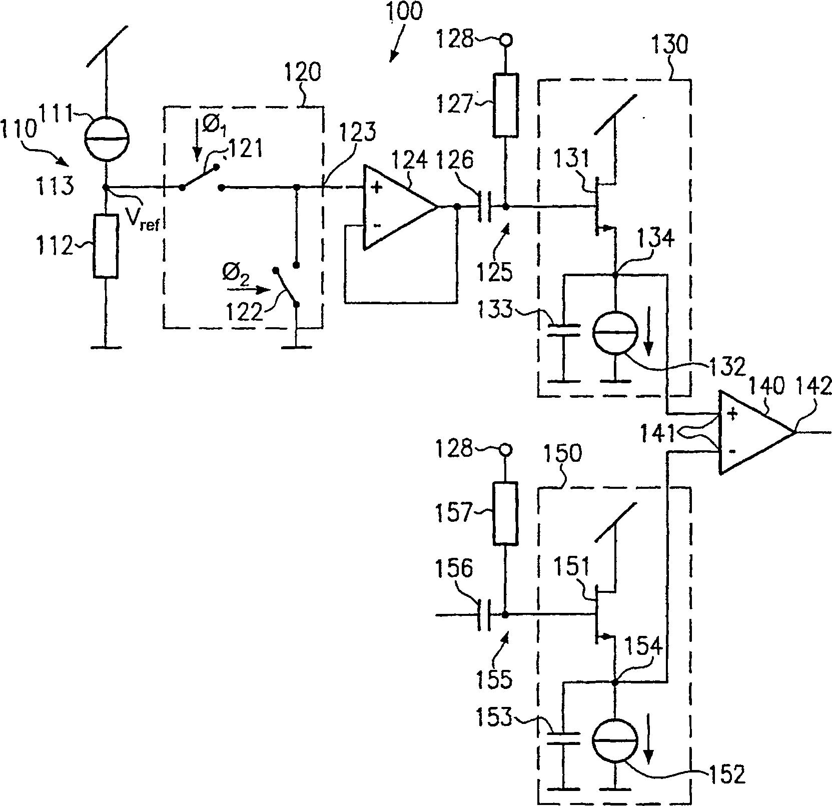
[0034] figure 1 A circuit diagram of a first exemplary embodiment of the RF signal voltage analysis circuit 100 is shown in which the RF signal voltage is compared with an AC reference voltage in this embodiment. The circuit 100 includes a DC reference voltage source 110 configured to generate a DC reference voltage Vref. in figure 1 In an exemplary embodiment, the reference voltage source 110 may include a constant current source 111 and a resistor 112 connected...


PUM


Abstract

The radio frequency signal voltage is determined from an AC reference voltage generated from a DC reference voltage and the envelope of the AC reference voltage is determined in an envelope detector, wherein the envelope detector (130) has a function substantially equivalent to that used to determine the radio frequency signal envelope The structure of the envelope detector (150). This AC reference voltage substantially cancels any DC offset, resulting in high stability against temperature and power supply variations. Furthermore, using approximately the same RF signal path for the RF signal and the reference signal can substantially compensate signal distortion caused by the RF signal path.

Description

Technical field [0001] The present invention mainly relates to an automated method for measuring radio frequency (RF) signals emitted by a transmitter, such as those used in wireless communication systems, such as wireless local area networks (WLAN), mobile phones, etc., and Specifically, the present invention relates to an on-chip detection system for RF signals to be easily implemented in an integrated automatic power level control system. Background technique [0002] As the demand for two-way wireless communication systems has been continuously increasing, no effort has been spared to develop low-cost and highly reliable transmitter / receiver devices (hereinafter referred to as transceivers). The key issue in this regard is the degree of integration of the corresponding transceivers that can be manufactured. In addition, in many applications, such as mobile phones, mobile computer applications, etc., low power consumption for long operating times with limited battery power is ...

Claims


Application Information

Patent Timeline
Patent Type & Authority Patents(China)
IPC IPC(8): H03G3/30H04B7/005
CPCH03G3/3052H03G3/3036H04W52/52
Inventor S·埃伦赖希L·达特K-H·桑丁
Owner GLOBALFOUNDRIES INC
Features
  • R&D
  • Intellectual Property
  • Life Sciences
  • Materials
  • Tech Scout
  • Unparalleled Data Quality
  • Higher Quality Content
  • 60% Fewer Hallucinations
Learn More