Lock body structure capable of stopping lock core twisted

A lock body and lock cylinder technology, which is applied in building locks, building structures, buildings, etc., can solve problems such as keyhole exposure, lock cylinder anti-twisting function, and restrictions.

Inactive Publication Date: 2009-09-16
秦才东
View PDF12 Cites 0 Cited by
  • Summary
  • Abstract
  • Description
  • Claims
  • Application Information

AI Technical Summary

Problems solved by technology

[0005] In order to solve the defects caused by the fixing of the lock body and the installation hole, a lock body structure that the lock core can rotate freely has occurred. This solution can solve the damage of reamer tools, but the keyhole is still exposed, and the structure needs to be dismantled and installed on the lock every time it is locked and opened, which is very difficult to operate and difficult to use in practice
As another example, Chinese patent 03223225 proposes to change the structure of the lock core to achieve a structure that can be idling without a key to open the lock core, but the improvement of this lock core makes the structure complicated, and the internal structure is easily damaged or deformed by the lateral force. It makes it difficult for the lock cylinder to have the ability of idling protection, and the keyhole is still exposed, the effect is not ideal
[0006] Looking at the above-mentioned schemes, in terms of improving the defects of the lock body, the two defects of keyhole exposure and lock body and lock hole fixing have not been improved in an all-round way. Either the keyhole is hidden, but the lock body and the lock hole are fixed; The lock hole can be rotated relative to each other, but the keyhole is still exposed, and both cannot be taken into consideration
[0007] Among all the above-mentioned schemes, the scheme of hiding the keyhole can prevent the large-scale violent tools from directly damaging the lock cylinder to a certain extent, but it does not completely solve the problem of violent unlocking, especially small-sized reamers (such as L-shaped or with keys) A small reamer with a similar shape) can enter the keyhole to break and unlock the lock; in the scheme where the lock cylinder and the lock hole can rotate relatively, either the operation is very complicated, or the structure of the lock body is very complicated, and the lock cylinder cannot be easily realized. Anti twist function
For a long time, the important problem of the lock cylinder being twisted has been ignored by the industry, and the use of related products has not been seen in practical applications.
[0008] Another defect of all the aforementioned schemes is: the installation of the lock head needs to cooperate with locked objects such as door panels or specific anti-theft locks for placing the lock, so as to form a door or other locking device, so that the manufacture and operation of the lock body The application field is restricted by the structure and design of the object to be locked, and it also brings great trouble to the installation of the lock body, and the above-mentioned lock bodies cannot form a lock device that is easy to manufacture and independent and universal, and cannot be widely used in a simple and convenient manner. Each locked field

Method used


Image

  • Lock body structure capable of stopping lock core twisted
  • Lock body structure capable of stopping lock core twisted
  • Lock body structure capable of stopping lock core twisted

Examples


Embodiment 1

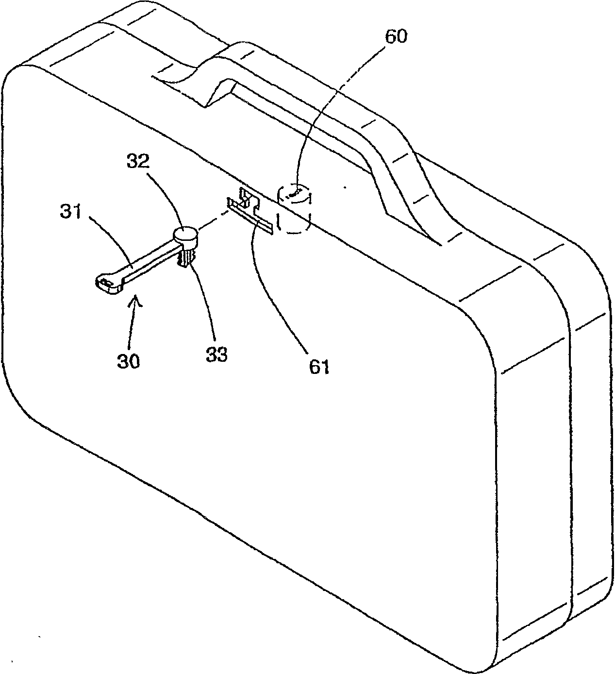
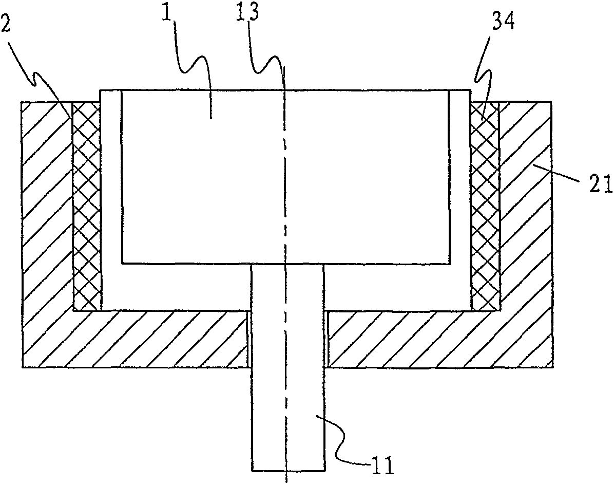
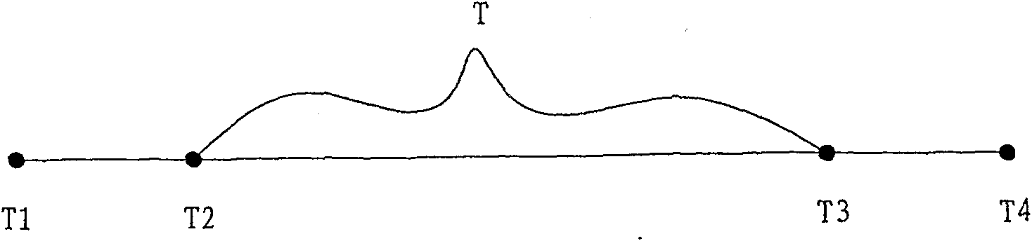
[0053] Such as figure 2 As shown, the lock body structure of the present invention includes a top lock head 1 (pushlock, which can be called a push lock in Chinese) arranged in the installation hole 2. The installation hole 2 is surrounded by side walls 21, and the lock bolt 11 is inserted and locked. Lock in the lock hole (not shown in the figure) of the object, and the top lock head 1 and the installation hole 2 are falsely fixed. Between the force and the torsional force that the lock cylinder is twisted. see Figure 2A , the torsional force of normally opening the lock body by the key is within the normal torsional force range T1-T2, and the lock core of the lock body 1 also has a twist-resistant or twist-resistant range T3-T4, the false fixation of the present invention is You can choose between these two ranges. Optimally, the strength T of the pseudo-fixation is between the maximum torsion force T2 that can be generated by the key to open the lock body normally and ...

Embodiment 2

[0059] see Figure 6, this embodiment is on the basis of embodiment 1, the installation hole is located in an additional lock body 4, the additional lock body 4 is provided with a through hole 43 for the deadbolt 11 to enter and exit and an opening 42 for the key to insert, the top The lock head 1 is arranged in the installation hole 41 of the additional lock body 4, and a pseudo-fixation is achieved between the installation hole 41 and the top lock head 1. In the figure, a circular tube-shaped step (or a rectangular step or an inner clip is used) The formed step) 40 realizes the axial tightening connection, of course, the elastic telescopic column pin 38 can also be used to realize false fixation. The additional lock body 4 can be made of a thin plate with a strip-shaped installation hole, or made of a leather sleeve, and its material can be selected from metal, high molecular polymer, wood or tempered glass, etc. The lock body can better protect the lock cylinder in it. The...

Embodiment 3

[0071] see Figure 11 , its principle and effect are exactly the same as those in Embodiment 2, and will not be repeated. The improvement is that an electronic alarm device 7 is further installed in the additional lock body 4 , and its switch 71 is connected by a wire 72 . The power switch 71 of the electronic alarm device 7 is similar to a bimetallic strip, and is triggered by the position movement of the deadbolt 11, further increasing the alarm prompt function.


PUM


Abstract

A lock body structure preventing wringing lock cylinder and an installation method thereof, comprising: a pushlock head arranged in mounting hole; a false fixation is provided between the pushlock head and the mounting hole, the joint strength of which is between the torque force of a key when the lock is normally opened and the torque force of the lock cylinder when it is wrung to be broken. When the lock is normally opened with the key, the pushlock head is fixed relative to the mounting hole, but when the lock body is wrung, the pushlock head rotates freely relative to the mounting hole. The present invention can thoroughly resolve the question that the lock cylinder is damaged by reamer type tools so that the lock would be unlocked illegally, so locking is more practical and reliable.

Description

technical field [0001] The invention relates to a lock, in particular to a lock body structure and an installation method capable of preventing the lock core from being twisted. Background technique [0002] There are two main defects in existing mechanical locks (such as various door locks, vehicle anti-theft locks, electric door locks, etc.). First, the keyhole of the lock cylinder is exposed, so that the core part of the lock, such as the lock cylinder, will directly face the violence of violent tools, and it is easy to be opened by electric drills, reamers, etc. Open by smashing, or by technical operations such as wires, sheet tools, etc. Its two, when installing, lock body and installation hole are fixed completely, are easy to be inserted into keyhole by tools such as reamer, screwdriver and wring the lock core and realize illegal opening. The keyhole is exposed, which provides enough convenient and spacious operating space for illegal unlockers, and the lock body an...

Claims


Application Information

Patent Timeline
Patent Type & Authority Patents(China)
IPC IPC(8): E05B17/14
Inventor 秦才东
Owner 秦才东
Why Eureka
Try Eureka