Parafoil platform and control method thereof

A platform and parafoil technology, applied in the field of parafoils, can solve the problems of reducing the reliability of the platform and occupying the available space inside the pod.

Pending Publication Date: 2019-03-08
GENERAL ENG RES INST CHINA ACAD OF ENG PHYSICS
View PDF0 Cites 0 Cited by
  • Summary
  • Abstract
  • Description
  • Claims
  • Application Information

AI Technical Summary

Problems solved by technology

[0003] 1. The realization of this control method must rely on the actuator (steering gear) arranged on the pod, and the introduction of the actuator will inevitably occupy the available space inside the pod. For platforms with tight space layout, it is obviously not possible. Pick
[0004] 2. At the same time, as an electronic device, if the actuator is removed from the platform, it will directly reduce the reliability of the platform

Method used


Image

  • Parafoil platform and control method thereof
  • Parafoil platform and control method thereof
  • Parafoil platform and control method thereof

Examples


Embodiment 1

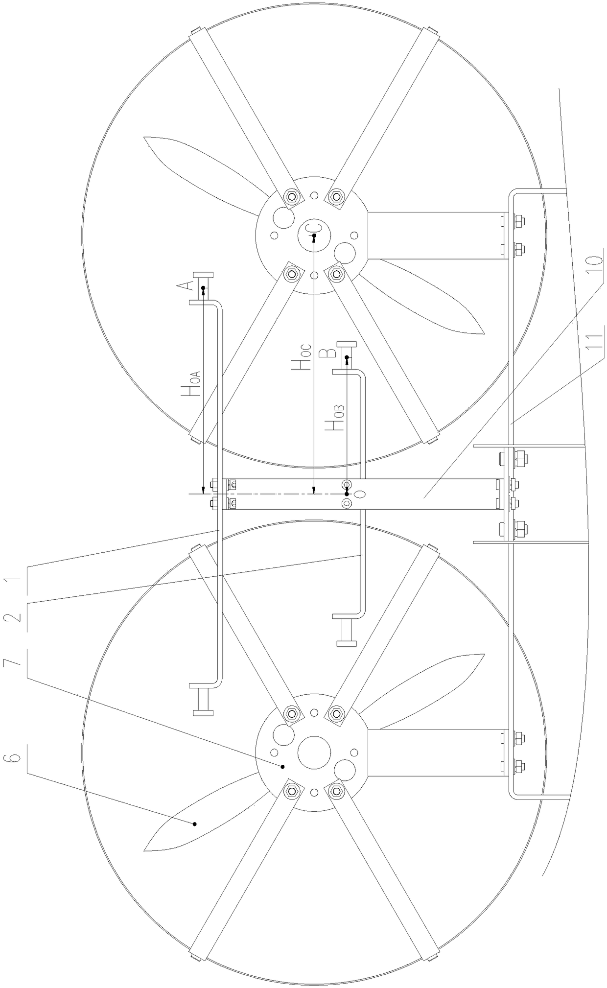
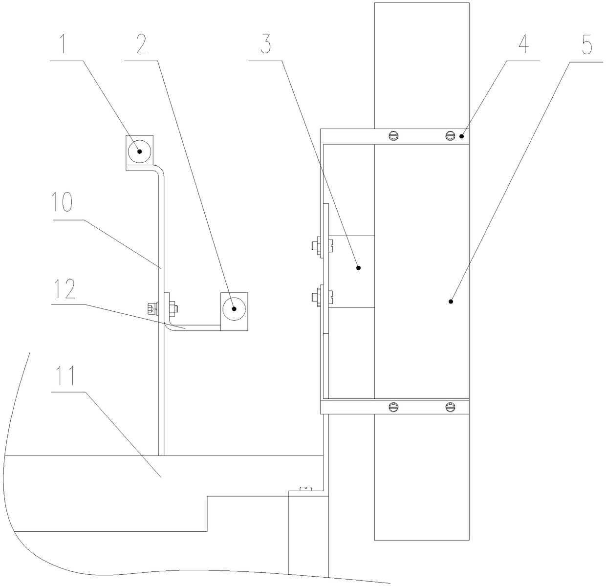
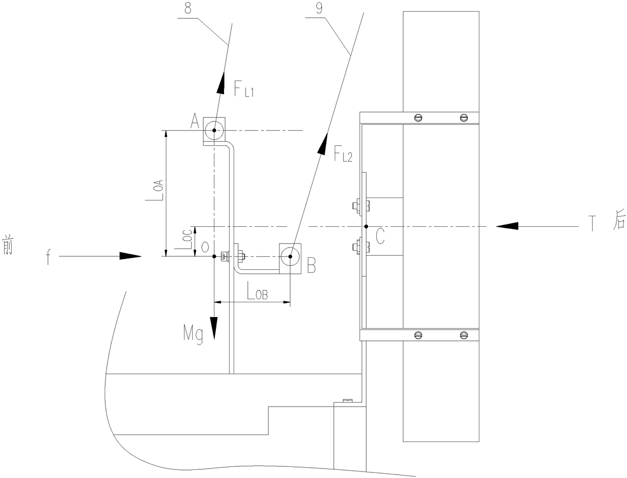
[0068] Example 1, such as figure 1 , figure 2 Shown:

[0069] The parafoil platform includes a parafoil, a pod platform 11, and two power units, each power unit is installed on the pod platform 11 through a connecting piece, the two power units are installed side by side, and the parafoil platform also includes;

[0070] Vertical bar 10; vertical bar 10 is installed on the upper part of pod platform 11, and vertical bar 10 is perpendicular to pod platform 11;

[0071] Suspension rod 1; the center of suspension rod 1 is connected with vertical rod 10 tops, and suspension rod 1 is parallel with gondola platform 11, and the two ends of suspension rod 1 are all connected with the suspension rope 8 of parafoil, and the upper ends of two suspension ropes 8 are all connected to each other. connected to the parafoil;

[0072] Cross bar 12; the first end of cross bar 12 is connected with the center of vertical bar 10, and cross bar 12 is vertical with suspension bar 1, vertical bar...

Embodiment 2

[0076] Example 2, such as figure 1 and figure 2 as shown,

[0077] The difference between this embodiment and Embodiment 1 is that the power unit includes:

[0078] Motor 3;

[0079] Propeller 6; the rotating shaft of motor 3 is fixedly connected with propeller 6 centers; the rotation plane of propeller 6 is parallel to vertical rod 10; the rotation plane of propeller 6 is perpendicular to pod platform 11; The projection center of the plane is the same as the distance from the centers of the propellers 6 of the two power devices; when the two propellers 6 are working, the directions of rotation are opposite;

[0080] Propeller cover 5; Propeller 6 is installed in the propeller cover 5;

[0081] Motor bracket 7; motor 3 is installed in the center of motor bracket 7, and motor bracket 7 is fixed on the connector; motor bracket 7 is externally connected with paddle cover 5 through multiple paddle bars 4.

[0082] The rotation direction of the two propellers 6 is opposite wh...


PUM


Abstract

The invention discloses a parafoil platform and a control method thereof. The parafoil platform is not equipped with a manipulating rope execution mechanism, so that an internal installation space ofa pod is saved, and work reliability of the platform is improved; the rotating directions of two propellers during work are opposite to each other, so that the problem of reverse twisting generated bywork of a platform equipped with one propeller is perfectly solved; the sizes selected by the two propellers are far lower than the size of the single propeller, and the total size of the two propellers is equivalent to the total size of the single propeller; the parafoil platform can be controlled by controlling the rotating speed of the propellers; by means of a control mode of the parafoil platform, the platform has the advantages of better internal space, higher reliability and greater convenience in operation.

Description

technical field [0001] The invention belongs to the technical field of parafoils, and in particular relates to a parafoil platform and a control method thereof. Background technique [0002] The conventional control structure of the parafoil platform is usually: the two suspension ropes of the parafoil are fixedly connected to the pod, and pass through the plumb surface of the center of gravity of the pod, and the two control ropes of the trailing edge of the parafoil are fixedly connected to the rear of the pod. On the two actuators (steering gear), power is provided by the propeller with the propeller cover on the pod at the same time. When performing left and right turns, etc., the control rope needs to be pulled down by the corresponding side servo, which will cause the shape of the trailing edge of the parafoil to change, and then change the aerodynamic force to realize the turning flight. [0003] 1. The realization of this control method must rely on the actuator (st...

Claims


Application Information

Patent Timeline
IPC IPC(8): B64C31/036B64D27/24B64F5/00
CPCB64C31/036B64D27/24B64F5/00
Inventor 邓坤谭晓军孙传杰钱立新卢永刚朱永清陈伟
Owner GENERAL ENG RES INST CHINA ACAD OF ENG PHYSICS
Why Eureka
Try Eureka