
Bottle cap cleaning machine

A washing machine and bottle cap technology, applied in cleaning methods and utensils, cleaning methods using gas flow, static electricity, etc., can solve the unreasonable design of the discharge needle tip blowing nozzle, reduce the air force, and increase the diameter of the air column And other issues

Inactive Publication Date: 2009-10-21
周捷明
View PDF6 Cites 0 Cited by
  • Summary
  • Abstract
  • Description
  • Claims
  • Application Information

AI Technical Summary

Problems solved by technology

The machine is mainly divided into three parts: the feeding area, the dust removal area, and the discharge area. The positive plate and high-voltage electric needle point (negative electrode) designed in the dust removal area are all set at the lower part of the bracket. The positive plate, high-voltage electric needle point ( The electric field generated between the negative electrodes) is outside the bottle cap, so that the bottle cap does not pass through a strong and concentrated electric field area during the cleaning process. When the negative ion wind blown out does not have sufficient charge, the dust removal effect is very poor; at the same time , the position of the blowing nozzle is far away from the position of the bottle cap, and the airflow it blows out is trumpet-shaped and continuously diffuses, which increases the diameter of the air column and reduces the force of the airflow, making it difficult for the dust to leave the bottle cap; in addition, the discharge needle tip and the bottle cap The design of the blowing nozzle as one is not completely reasonable

Method used


Image

  • Bottle cap cleaning machine

Examples


Embodiment Construction

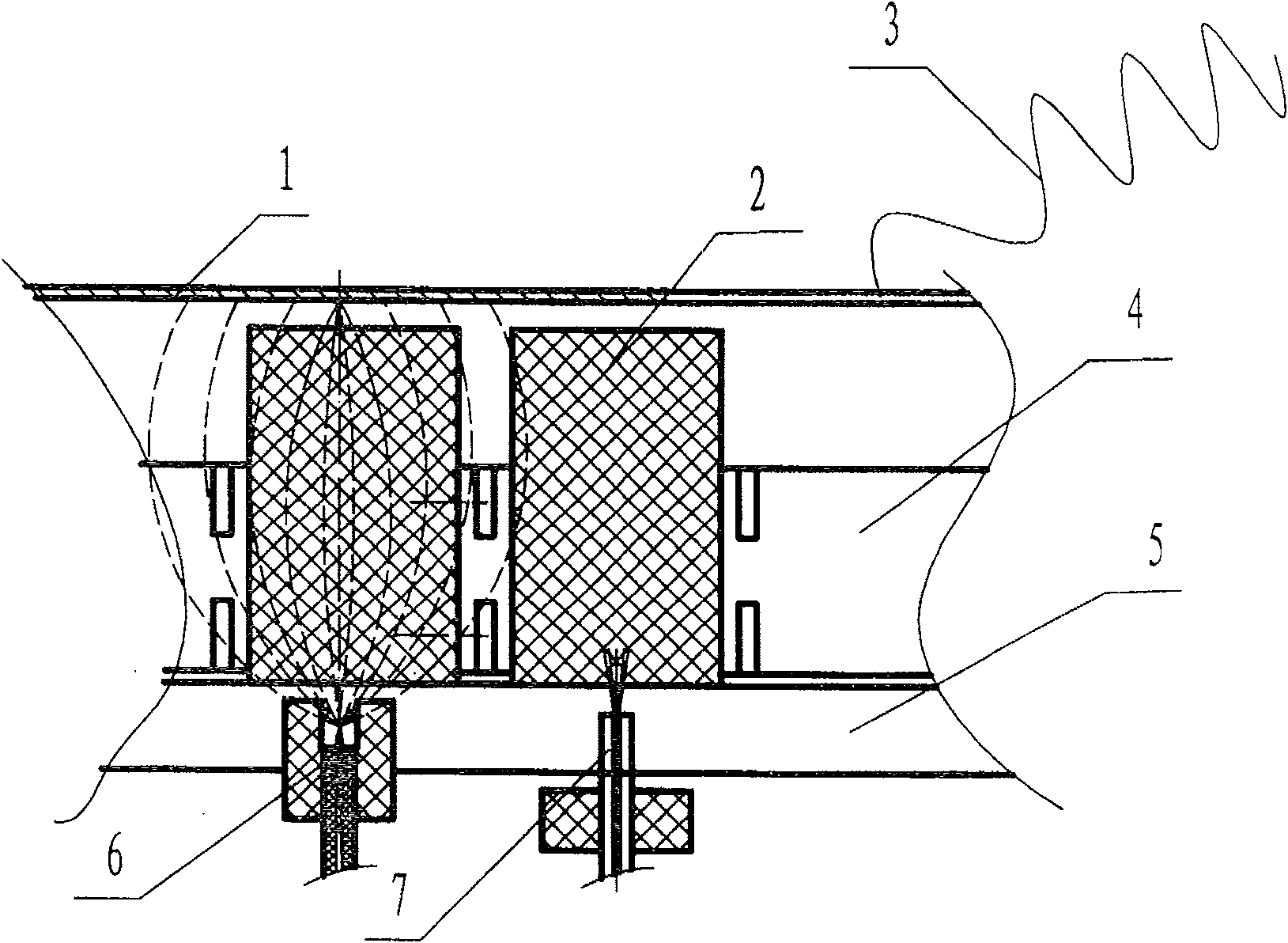
[0010] refer to figure 1 , the dust removal area of ​​the bottle cap cleaning machine includes blowing nozzle 7, high-voltage electric needle tip 6, height adjustment cover 1, insulation bracket 5, insulation feeding tray 4, grounding wire 3, etc.; height adjustment cover 1 is located in the insulation feeding The upper part of the tray 4; the blowing nozzle 7 and the high-voltage electric needle tip 6 are spaced apart, and are separately arranged on the lower part of the insulating feeding tray 4; the lower part of the insulating feeding tray 4 is also provided with an insulating bracket 5, a grounding wire 3 and a height adjustment cover The board 1 is connected; and the upper end of the air blowing nozzle 7 and the upper end of the high voltage electric needle point 6 are located at the inner space of the insulating bracket 5; or only the upper end of the air blowing nozzle 7 is located at the inner space of the insulating bracket 5.

[0011] When in use, when the bottle ca...


PUM


Abstract

The invention relates to a bottle cover cleaning machine with electrostatic dedusting. The lower part of an insulated feeding disc in the dedusting area of the bottle cover cleaning machine is provided with an insulated bracket and a grounding wire connected with a height adjusting cover plate; blowing nozzles are intermittently separated from high-voltage acusector tip; furthermore, the upper end of the blowing nozzle and the upper end of the high-voltage acusector tip are arranged in the internal space of the insulated bracket. Owning to the insulated bracket, original anode plate can be replaced by the height adjusting cover plate, thus leading a electric field to be generated between the height adjusting cover plate and the high-voltage acusector tip, leading the bottle cover to fully pass through the electric field, eliminating static through grounding the height adjusting cover plate and being easier to dedust. Furthermore, the upper end of the blowing nozzle is arranged in the internal space of the insulated bracket, which is closer to the bottle cover, thus reinforcing dust blowing function by strong airflow which is generated.

Description

technical field [0001] The invention relates to a bottle cap cleaning machine for electrostatic dust removal. Background technique [0002] At present, various plastic products are prone to static electricity during the process of manufacturing and handling, and a large amount of dust and various tiny particles are adsorbed on the surface. The acceleration and force generated by the ordinary airflow dust blowing method on these dust and various tiny particles are too small, which is far from enough to overcome the electrostatic adsorption force and make them detach from the surface of plastic products. [0003] There is an existing bottle cap cleaning machine, which uses an electrostatic generator to perform high-voltage discharge of the electric needle tip, and the negative ions generated make the compressed air blown out by the air blowing nozzle into negative ion wind; When cleaning the surface, the dust is separated from the surface of the plastic product and then disch...

Claims


Application Information

Patent Timeline
Patent Type & Authority Patents(China)
IPC IPC(8): B08B5/02H05F3/04H05F3/02
Inventor 周捷明
Owner 周捷明
Learn More