
Automatic music leaf turner

An automatic page-turning technology, which is applied in the field of page-turning devices, can solve the problems of slow page-turning speed, affecting the player's viewing of music scores, and lagging behind, and achieves the effects of fast speed, small space occupation, and easy operation

Inactive Publication Date: 2009-11-04
刘苏
View PDF8 Cites 2 Cited by
  • Summary
  • Abstract
  • Description
  • Claims
  • Application Information

AI Technical Summary

Problems solved by technology

But this patent has the following disadvantages: 1. only one side of the music stand is provided with an L-shaped page-turning swing arm and a clip, so it can only clamp a corner of one side of the score paper, and there is an L-shaped page-turning swing arm and a clip when turning pages The music paper on this side of the clip will be turned over synchronously with the L-shaped page-turning swing arm and the clip, while the music paper on the other side of the L-shaped page-turning swing arm and the clip will fall later due to air resistance, which is easy to affect The player's view of the score
②Because a series of gears and racks are driven by the transmission chain, the page turning speed is slow and there is a defect of lag

Method used


Image

  • Automatic music leaf turner
  • Automatic music leaf turner
  • Automatic music leaf turner

Examples


specific Embodiment approach 1

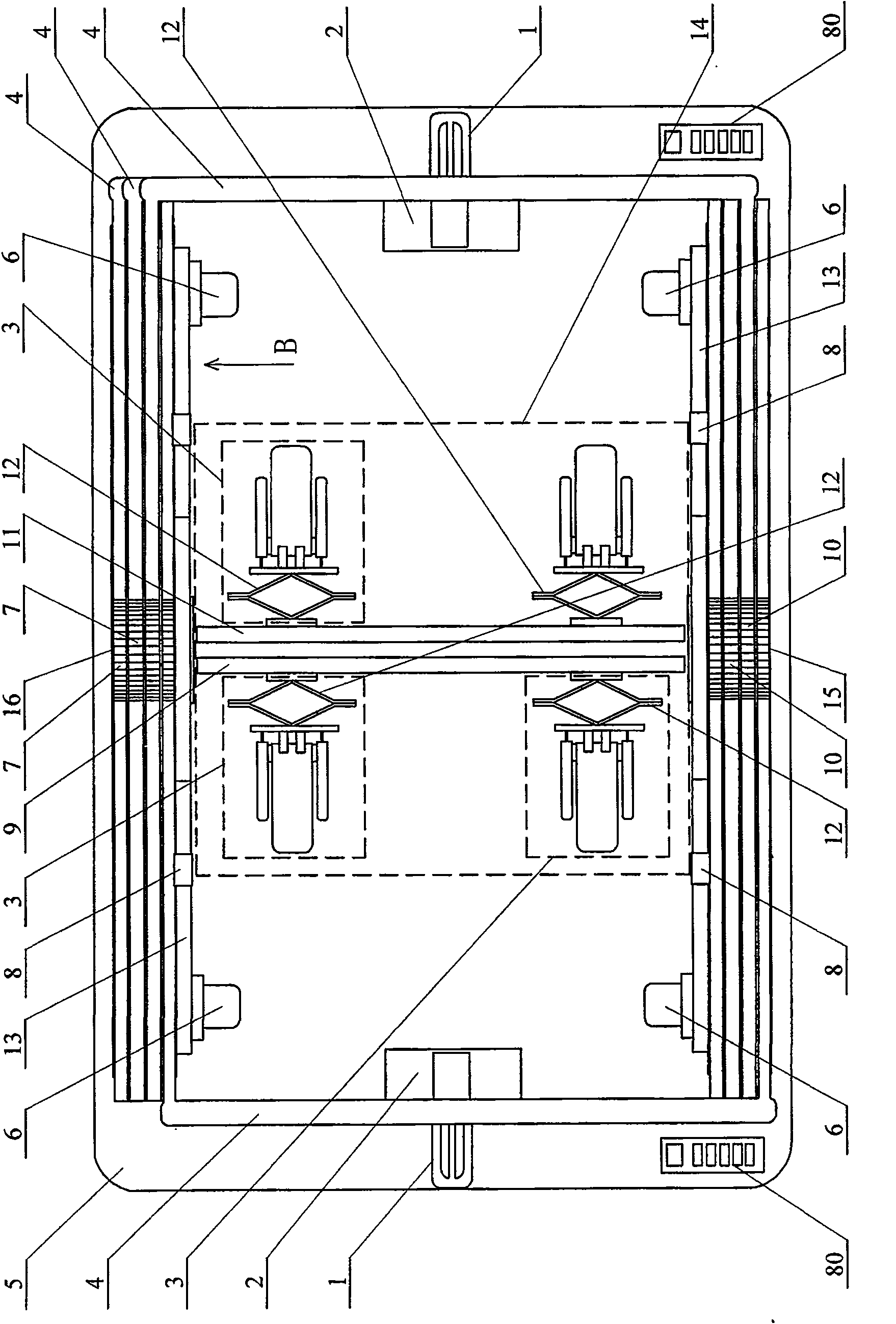
[0006] Specific implementation mode one: (see Figure 1 ~ Figure 4 , Figure 12 ) This embodiment includes music paper clip 2, "door"-shaped page turning connecting arm 4, flat plate 5, transmission gear 10, support wheel 7, music score fixing device 14, first dial column 31, rack pull bar 32, second dial Column 36, third shifting column 41, first controller 57 of rack pull rod, second controller 84 of rack pull rod, rack pull rod guard groove 85, page turning rack 86, page turning driver 89 and rack support Plate 174, a transparent groove 15 is opened on the lower side of the front of the flat panel 5, and a slot 16 is opened on the upper side of the front of the flat panel 5, the transmission gear 10 is arranged in the transparent groove 15, and the support wheel 7 is arranged on the said transparent groove 15. In the groove 16, the "door" shaped page turning connecting arm 4 is arranged on the front of the flat panel 5, and one end of the "door" shaped page turning connect...

specific Embodiment approach 2

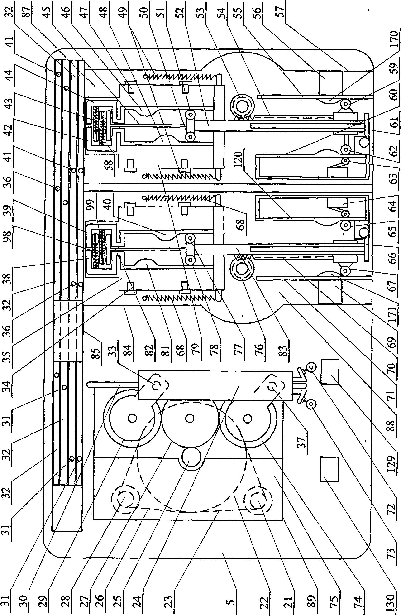
[0007] Specific implementation mode two: (see figure 2 ) The page turning driver 89 of the present embodiment comprises a first motor 21, a first drive wheel 22, a first transmission belt 23, a linkage plate 24, a first gear 25, a second transmission belt 26, a second gear 27, a second motor 28, The third gear 29, the driving lever 30, the first connecting shaft 33, the second connecting shaft 37, the fourth gear 74 and the first mounting plate 75, the second gear 27, the third gear 29 and the fourth gear 74 are arranged on the second gear in turn. On one side of a mounting plate 75, the second gear 27 meshes with the third gear 29 and the fourth gear 74 respectively, one end of the first connecting shaft 33 is connected with the third gear 29, and the other end of the first connecting shaft 33 Connected with the linkage plate 24, one end of the second connecting shaft 37 is connected with the fourth gear 74, the other end of the second connecting shaft 37 is connected with t...

specific Embodiment approach 3

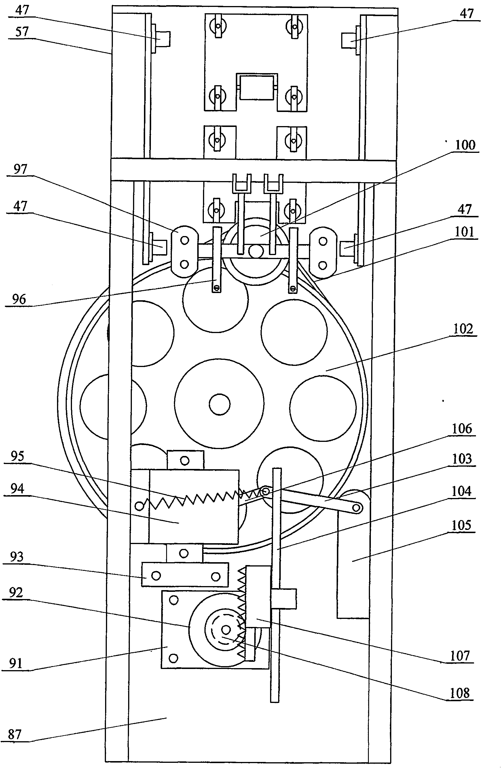
[0008] Specific implementation mode three: (see figure 2 , image 3) The first regulator 57 of the rack pull rod of the present embodiment is composed of the first toggle lever 42, the first tension spring 43 of the toggle lever, the second toggle lever 44, the first slide bar 45, and four first driving slides. Roller 47, two extension springs 49 of the first drive slide plate, the first slideway wheel 50, the second slideway wheel 51, the first slideway wheel drive plate 52, the fifth gear 53, the first slideway wheel drive plate The rack 54, the first driving rod slideway 55, the second extension spring 58 of the toggle lever, the second travel switch slideway 60, the first slideway wheel drive plate reset card seat 61, the first travel switch roller 62, the second A travel switch 63, a first driving slide 79, a first main board 87, a first starter motor fixing base 91, a first starter motor 92, a first motor forward and reverse automatic switch frame 93, a first motor for...


PUM


Abstract

An automatic page-turner, which relates to a page-turner. The purpose of the present invention is to solve the problem that the existing page-turner is only provided with an L-shaped swing arm and a clip on one side of the music stand, and the page-turning of the sheet music cannot fall synchronously. , It is easy to affect the player's viewing of the score. Relying on the transmission chain to drive a series of gears and racks, the page turning speed is slow and there is a problem of lag. One end of the "door"-shaped page-turning connecting arm of the present invention is fixedly connected to the transmission gear, the other end of the "door"-shaped page-turning connecting arm is fixedly connected to the support wheel, and the spectrum paper clip is fixed in the middle of the "door"-shaped page-turning connecting arm Positionally, the second regulator of the rack pull rod is fixed at the position between the back page turning driver of the tablet and the first regulator of the rack pull rod. The music paper clip of the present invention clamps the middle part of the edge of the music paper, and the music paper and the page-turning connecting arm are turned over synchronously, so that the performer can see the content of the music score on the next page in time. Sheet music can be turned forward or backward continuously. It is easy to carry, takes up little space and is easy to operate.

Description

technical field [0001] The invention relates to a page turner. Background technique [0002] When instrumental music is played or practiced, it is inseparable from the page turning of the score, such as piano performance or accompaniment often requires a person who is specially responsible for turning the score to sit next to the player. The instrumental performances of large and small orchestras such as symphony orchestras and national orchestras are in progress, and two people share a score, so one of the two people must stop and turn the score during the music, so that the music being played will be affected by the score. The effect of playing. The Chinese patent number is ZL200620114562.X, the authorized announcement date is July 4, 2007, the authorized announcement number is CN2918075Y, and the utility model patent named "pedal page turner" discloses a pedal-controlled page turner , this patent solves the problem of page-turning during instrumental music performance. ...

Claims


Application Information

Patent Timeline
Patent Type & Authority Patents(China)
IPC IPC(8): B42D9/04B42D9/00
Inventor 刘苏靳铁梅刘天祺
Owner 刘苏
Learn More