Supercharge Your Innovation With Domain-Expert AI Agents!

Current control device

A current control and current technology, applied in lighting devices, control/regulation systems, electric light sources, etc., can solve problems such as reliability doubts, product reliability doubts, bipolar transistor overheating, etc., and achieve the best reliability Effect

Inactive Publication Date: 2009-11-04
CPT TECH GRP
View PDF6 Cites 0 Cited by
  • Summary
  • Abstract
  • Description
  • Claims
  • Application Information

AI Technical Summary

Problems solved by technology

[0005] However, this circuit is only an open-loop control system, that is, this circuit does not have any feedback control, so once the LED strings in the system fail (for example, some LEDs in the LED string have a short-circuit fault) , or the error value of the total cut-in voltage of the LED string is too large (for example, because the temperature characteristics of each LED are slightly different, causing each LED string to form a large total cut-in voltage difference after power-on), due to The system has no feedback control, so this state cannot be detected, so the bipolar transistor on the current mirror will be subjected to a considerable voltage and current, which will cause the temperature of the bipolar transistor to rise continuously, thereby causing the bipolar transistor to There is a risk of overheating, which raises doubts about the reliability of products using this technology
[0006] In addition, patents such as U.S. Patent No. 6,556,067 and Patent No. 6,636,104 also use an open-loop control method such as a current mirror to force the currents of each group of LED strings to reach the same level, thereby completing the control of brightness uniformity, so there is also a reliable degrees of doubt

Method used


Image

  • Current control device
  • Current control device
  • Current control device

Examples


Embodiment Construction

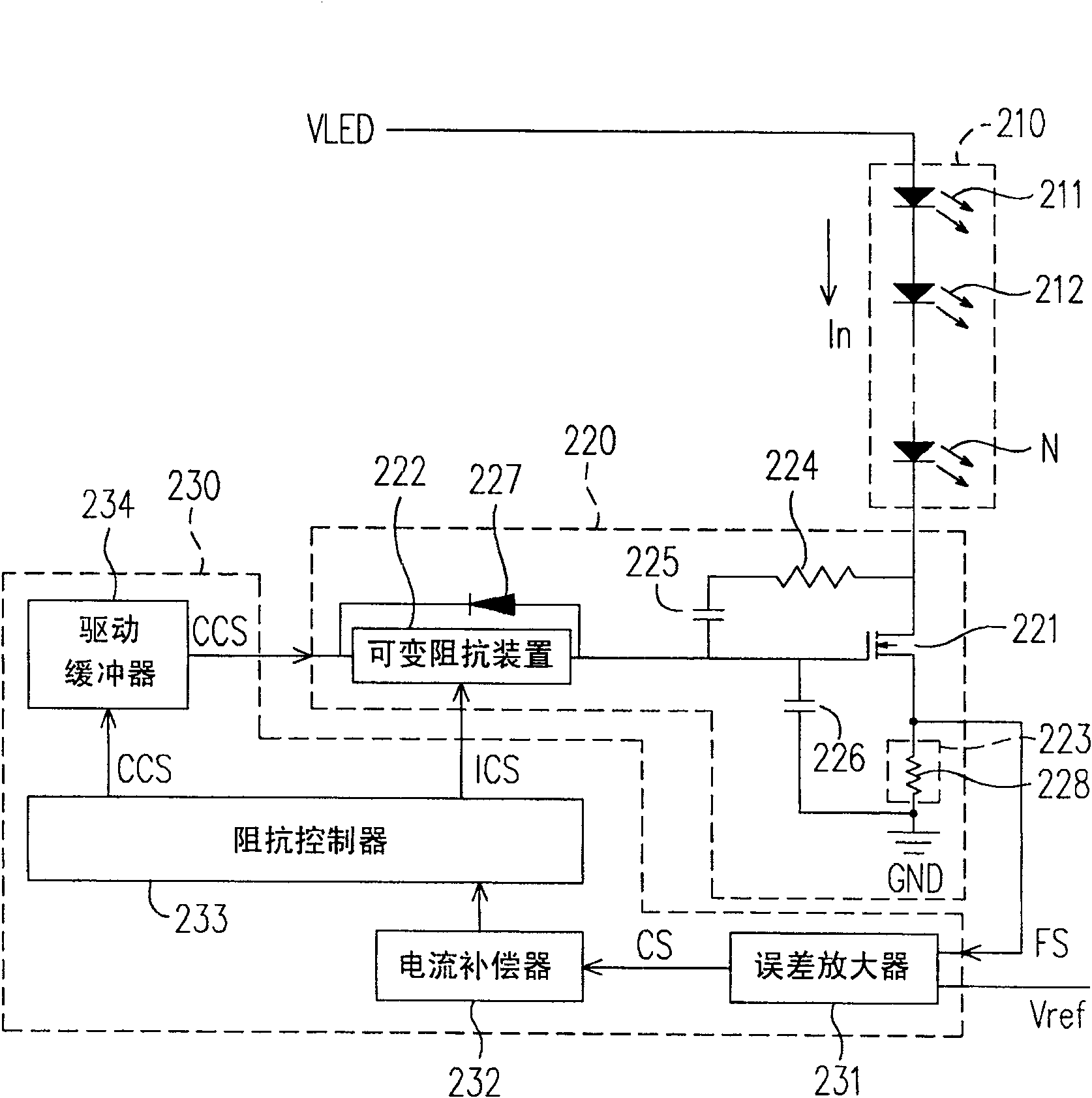
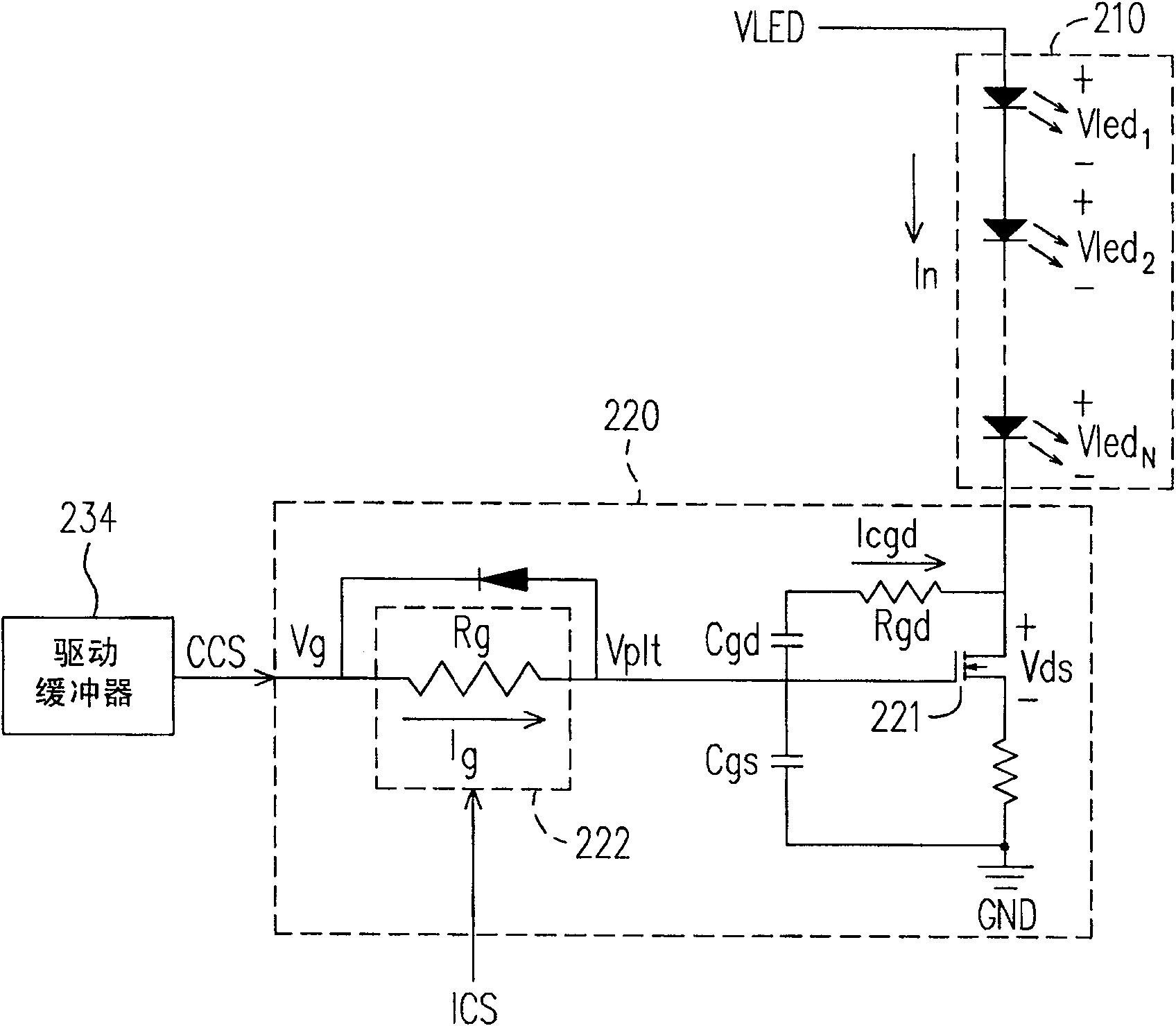
[0022] figure 2 It is a current control device according to an embodiment of the present invention. Please refer to figure 2 , the current control device is suitable for controlling the current In flowing through the light-emitting element string 210. In this embodiment, the light-emitting element string 210 is composed of light-emitting diodes 211, 212-N, and one end of the light-emitting element string 210 is electrically connected to to the power supply voltage VLED (that is, the first potential). However, the light emitting device string 210 is not limited to be composed of light emitting diodes.

[0023] The current control device includes a current adjustment unit 220 and a control unit 230 . The current adjustment unit 220 is used to detect the current In of the light-emitting element string 210, and generate a feedback signal FS accordingly, and control the light-emitting element string 210 and the ground voltage GND (ie, the second potential) according to the con...


PUM


Abstract

The invention discloses a current control device, which is suitable for controlling the current flowing through a string of light-emitting elements, wherein one end of the string of light-emitting elements is electrically connected to a first potential. The current control device includes a current adjustment unit and a control unit. The current adjustment unit is electrically connected between the second potential and the other end of the light-emitting element string to detect the current of the light-emitting element string, thereby generating a feedback signal, and controlling the light-emitting element string according to the conduction control signal and the impedance control signal The resistance value between the second potential and the second potential, and then control the current of the light-emitting element string. The control unit is electrically connected to the current adjustment unit to receive and compare the values ​​of the reference signal and the feedback signal to generate a comparison result, and perform current compensation on the comparison result, and convert the comparison result after current compensation into conduction control signal and impedance control signal.

Description

technical field [0001] The present invention relates to a current control device, and in particular to a current control device which utilizes feedback control to adjust the current flowing through the LED string to adjust the brightness of the LED string. Background technique [0002] In the Light Emitting Diode (LED) backlight of a Liquid Crystal Display Television (LCD TV for short), a large number of light emitting diodes are required to achieve the same brightness as that of a Cold Cathode Fluorescent Lamp (Cold Cathode Fluorescent Lamp, short for short). CCFL) equivalent specifications. In general design, in order to reduce the number of LED driving integrated circuits (Driving Integrated Circuit) and the total driving current of LEDs, the LED backlight often needs to use a design circuit in which multiple LEDs are lit in series. This method can not only reduce the number of groups of the driving integrated circuits, but also reduce the total driving current of the li...

Claims


Application Information

Patent Timeline
Patent Type & Authority Patents(China)
IPC IPC(8): H05B33/08G05F1/56H05B44/00
CPCY02B20/347Y02B20/30
Inventor 赵翰楀陈弼先林信彰
Owner CPT TECH GRP
Features
  • R&D
  • Intellectual Property
  • Life Sciences
  • Materials
  • Tech Scout
  • Unparalleled Data Quality
  • Higher Quality Content
  • 60% Fewer Hallucinations
Learn More