Push switch

A switch and button technology, applied in textiles and papermaking, sewing equipment, sewing machine ring mechanism, etc., can solve the problem of not being able to reduce the size of the movable part 34 in the moving direction, and achieve the effect of miniaturization

Inactive Publication Date: 2009-12-02
ALPS ALPINE CO LTD
View PDF7 Cites 0 Cited by
  • Summary
  • Abstract
  • Description
  • Claims
  • Application Information

AI Technical Summary

Problems solved by technology

[0027] However, since the wing portions 38d are provided on both sides of the base portion 38a of the movable contact member 38, the moving direction of the movable member 34 and the size in the direction perpendicular to the moving direction cannot be reduced, resulting in an increase in size. The problem

Method used


Image

  • Push switch
  • Push switch
  • Push switch

Examples


Embodiment Construction

[0066] An embodiment of the push button switch of the present invention will be described below with reference to the accompanying drawings.

[0067] 【Example】

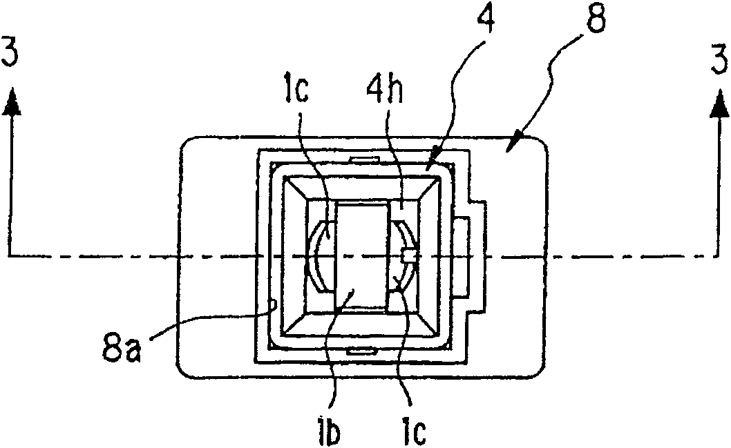
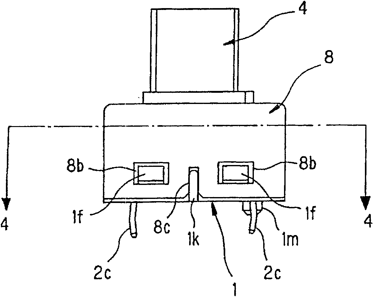
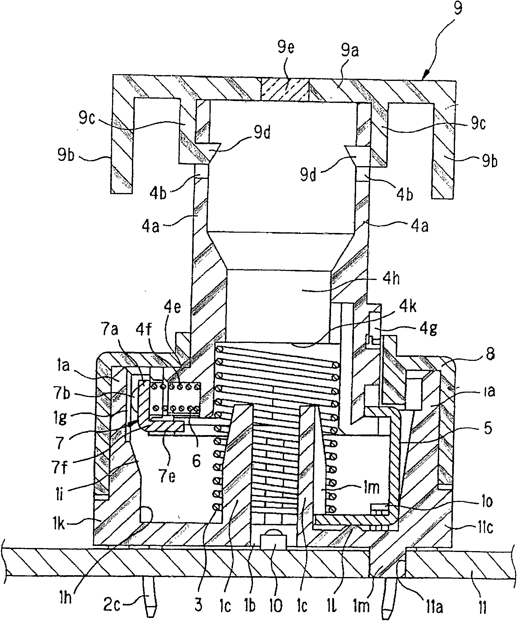
[0068] Embodiments of the present invention are described below with reference to the accompanying drawings, figure 1 It is a top view of the push button switch of the embodiment of the present invention, figure 2 yes figure 1 The front view of the pushbutton switch shown, image 3 is along figure 1 sectional view of the 3-3 line, Figure 4 is along figure 2 sectional view of line 4-4, Figure 5 It is an explanatory diagram showing the vicinity of the fixed contact of the housing of the push button switch according to the embodiment of the present invention, Figure 6 It is an exploded perspective view of a push button switch according to an embodiment of the present invention, Figure 7 From Figure 6 The exploded perspective view of the rear view, Figure 8 It is a cross-sectional view showing a state...


PUM


Abstract

In order to provide a small push button switch that can arrange the display part and the light source close to each other with a simple structure and can efficiently illuminate the display part, it is provided with: A display portion is formed on the upper end, and an insertion hole facing the through hole is formed on the bottom surface. The light source is accommodated in the insertion hole and the through hole; the through hole is formed in a linear shape along the pressing direction. Alternatively, in order to provide a miniaturized push button switch, it is provided with: a housing with a pair of fixed contacts extending in parallel along the pressing operation direction; a movable contact part held on the above-mentioned operation shaft and elastically The component is elastically biased, and is provided with a movable contact composed of a pair of protruding parts that are respectively in elastic contact with the above-mentioned fixed contacts; the contact-separation guide part is provided on the above-mentioned housing, and is in the closed position following the pressing operation. The upper portion is in contact with a portion between the pair of protruding portions, and the movable contact is separated from the fixed contact.

Description

technical field [0001] The present invention relates to a push button switch having an illumination structure for locking a power window or the like. [0002] In addition, the present invention also relates to a push button switch in which a fixed contact member is provided on the inner surface of a casing, and a movable contact member is provided on an operation shaft that can be contacted and separated from the fixed contact member. Background technique [0003] As a push button switch with an illumination structure, the structure of the first conventional example shown in Patent Document 1 is known, such as Figure 9 shown. [0004] As shown in this figure, the push button switch is made of the following parts: a button 21 with a light-transmitting display portion on the front; an escutcheon 23 of opaque material that is inserted into the button hole 22 of the button portion 21; A printed circuit board 25 of an opaque material with a switch 24 operated by the button 21 o...

Claims


Application Information

Patent Timeline
Patent Type & Authority Patents(China)
IPC IPC(8): D05B57/36
Inventor 森俊晴泽田谦次佐佐木敦实
Owner ALPS ALPINE CO LTD
Why Eureka
Try Eureka