Electrode and electric dirt collector

A technology for electric dust collectors and electrodes, which is applied in the field of electric dust collectors and can solve problems such as the reduction of the dust collection area

Inactive Publication Date: 2009-12-09
MIDORI ANZEN
View PDF6 Cites 0 Cited by
  • Summary
  • Abstract
  • Description
  • Claims
  • Application Information

AI Technical Summary

Problems solved by technology

[0008] However, due to the above-mentioned electrode holding member, there is a problem that the dust suction area of ​​the electrode (the surface area of ​​the electrode that is in contact with the air containing dust) becomes small.

Method used


Image

  • Electrode and electric dirt collector
  • Electrode and electric dirt collector
  • Electrode and electric dirt collector

Examples


no. 1 approach

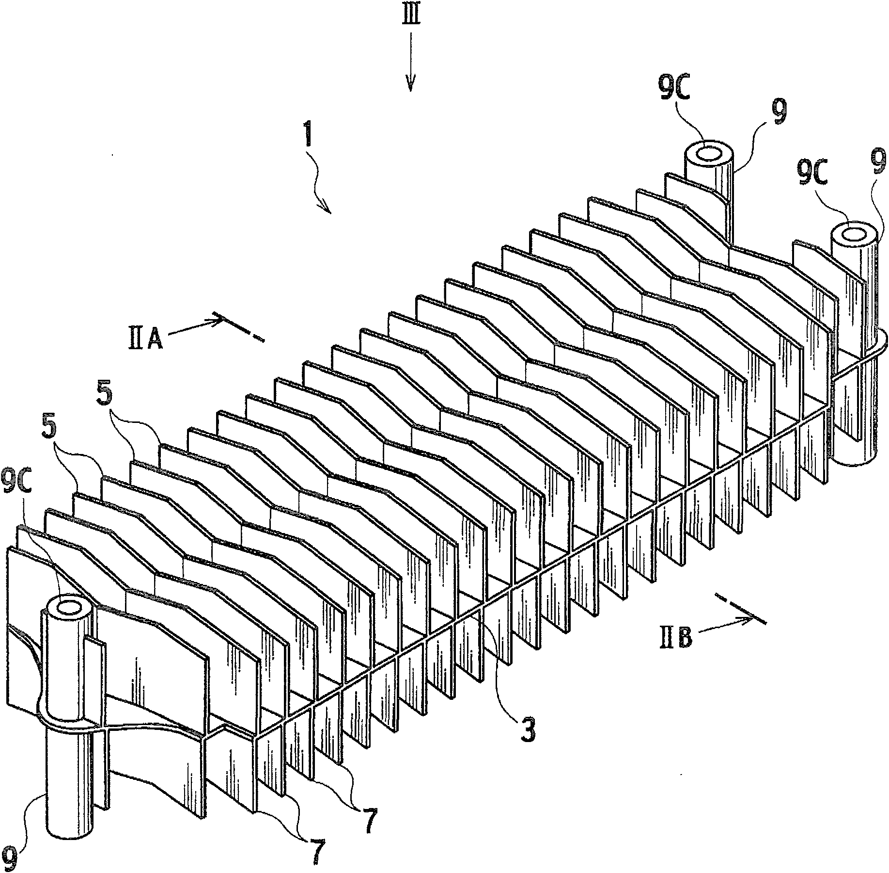
[0037] figure 1 It is a perspective view which shows the schematic structure of the electrode 1 of the electric dust collector which concerns on 1st Embodiment of this invention.

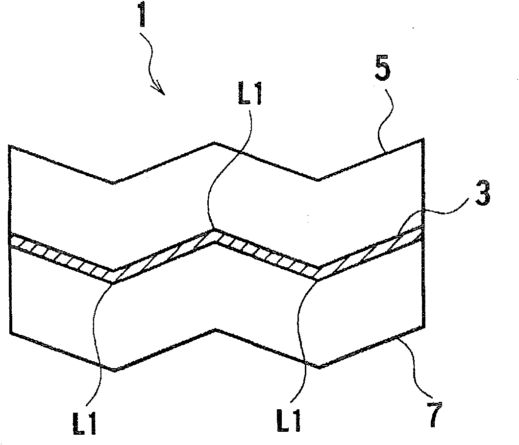
[0038] figure 2 yes means figure 1 A diagram of the section II A-II B in the middle.

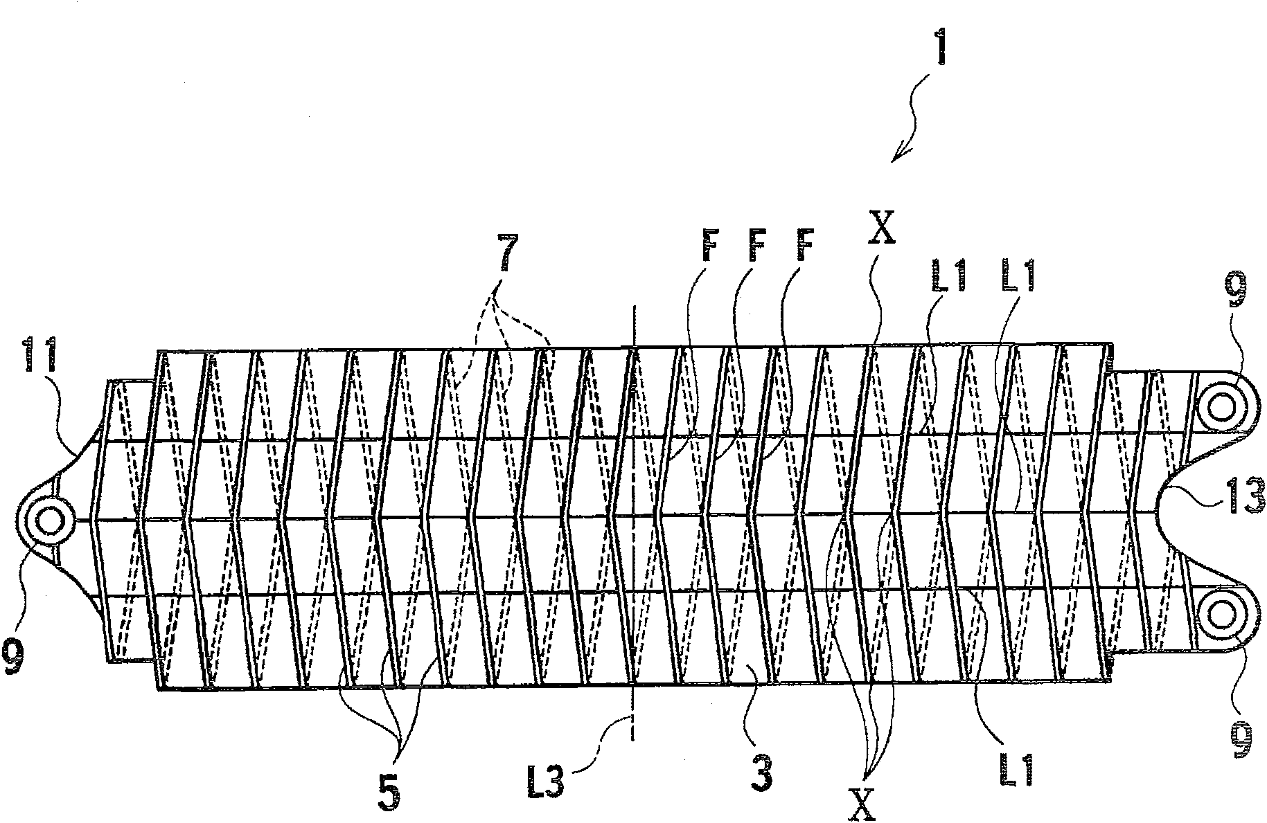
[0039] image 3 yes means figure 1 The figure in the direction of III is a plan view showing a schematic configuration of the electrode 1 .

[0040] The electrode (for example, the capture-side electrode) 1 is used as an electrode of an electric dust collector for capturing charged dust, and is equipped with a conductive plate-shaped base member 3 .

[0041] In addition, first ribs 5 and second ribs 7 formed of conductive members are provided on each of both surfaces in the thickness direction of the above-mentioned plate-shaped base member (base plate) 3 .

[0042] In addition, a plurality of the first ribs 5 are provided on one surface of the base member 3 at a predetermined interval, and a plurality of t...

no. 2 approach

[0112] Figure 10 is a perspective view showing a schematic configuration of an electrode 1e according to a second embodiment of the present invention, and is the same as figure 1 The figure corresponding to the III direction in the middle.


PUM


Abstract

An electrode (1) has a plate-shaped base member (3) and a plurality of ribs (5, 7) provided on both sides of the plate-shaped base member (3) with predetermined intervals, in order to improve the The bending moment generated by the load in the direction perpendicular to the base member (3) in the direction at right angles to the length direction and width direction of the base member (3) is the axis extending in the width direction of the base member (3). Rigidity of the bending moment at the center, the above-mentioned base member (3) bends or bends.

Description

technical field [0001] The present invention relates to an electrode and an electrostatic precipitator using the electrode, and more particularly to an electrostatic precipitator in which the electrode includes a curved plate member and a plurality of curved ribs erected on both surfaces of the plate member. Background technique [0002] For example, an electric dust collector that collects dust contained in the air generally includes an electrode for charging the dust and an electrode for capturing the dust charged by the charging electrode. [0003] Conventionally, as the above-mentioned electrodes, it is known to have a plate-shaped base member standing substantially at right angles from one surface of the base member in the thickness direction and extending in the width direction of the above-mentioned base plate while leaving a predetermined distance between each other. A plurality of flat ribs provided in parallel on each surface of the base member in the thickness dir...

Claims


Application Information

Patent Timeline
Patent Type & Authority Patents(China)
IPC IPC(8): B03C3/47B03C3/08B03C3/12
CPCB03C3/47B03C3/12B03C3/08
Inventor 胜村真一郎真木教雄
Owner MIDORI ANZEN
Why Eureka
Try Eureka