Transport device

a technology of transport device and sleeve, which is applied in the direction of roof covering, roof covering insulation, building components, etc., can solve the problems of reducing predictability and high throughput speed, and achieve the effect of limiting pitch, reducing predictability, and favourable effect on sorting capacity of the devi

Active Publication Date: 2011-12-06
VAN RIET EQUIP
View PDF10 Cites 5 Cited by
  • Summary
  • Abstract
  • Description
  • Claims
  • Application Information

AI Technical Summary

Benefits of technology

[0005]By providing the transport device according to the invention with pusher shoes which comprise a guiding construction which, in co-action with the guide means of the frame, brings about the displacement of the pusher shoes, wherein the guiding construction comprises a guide pin with a guide body arranged thereon, wherein the guide pin comprises at least two portions of differing diameter, wherein the guide means comprise a guide channel in which the guide pin can engage, and wherein the guide channel, and preferably the depth thereof, progresses such that at first engagement the portion of the guide pin with the largest diameter engages in the guide channel, and with further engagement a portion with a smaller diameter. A transport device is obtained wherein a high throughput speed can be achieved without this causing problems in the transfer of objects, in particular relatively small objects. An advantage is hereby also achieved particularly at a switch, wherein among other advantages the switching time of the switch is reduced.
[0008]It is advantageous to provide the transport device with carriers wherein the pitch between two pusher shoes situated on successive carriers amounts to a maximum of 130 mm. In the context of this application the pitch is defined as the horizontal distance (or, in the case the moving track runs obliquely, the distance measured parallel to the moving track) between the axes of two successive pusher shoes. The transport device according to the invention is preferably further characterized in that the pitch amounts to a maximum of 115 mm, more preferably a maximum of 105 mm, and most preferably lies between about 100 and 105 mm. By embodying the guiding construction of the pusher shoes according to the invention it becomes possible to limit the pitch. This has a favourable effect on the sorting capacity of the device.
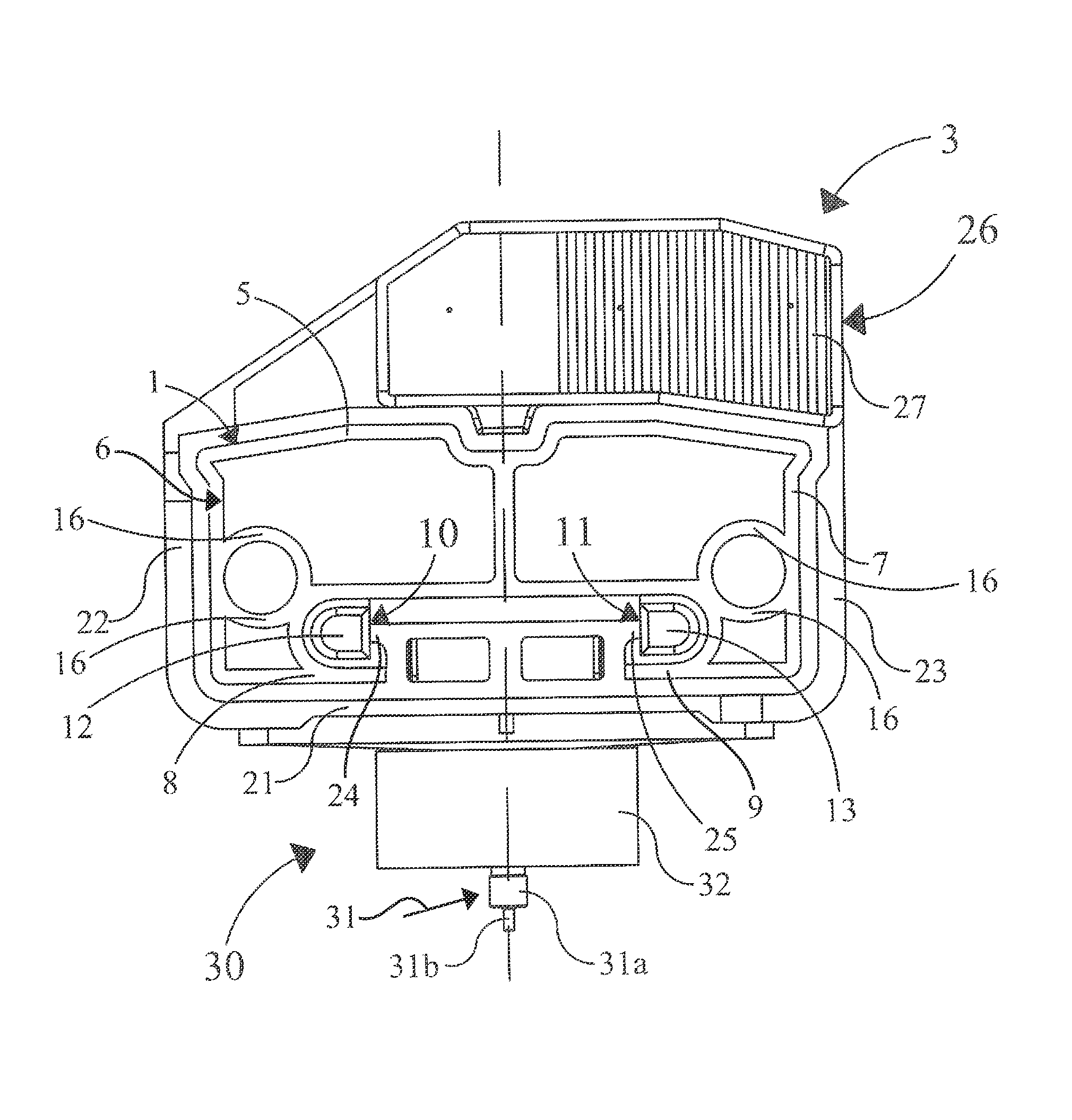
[0009]A further preferred embodiment of the transport device according to the invention is characterized in that at least some of the carriers have an arcuate upper surface in the width direction thereof. Although the radius of curvature of the arcuate upper surface can be selected within broad limits, it is advantageous if it lies between 100-800 mm, more preferably between 150-500 mm, most preferably between 200-300 mm. By giving the upper surface of at least some of the carriers an arcuate form a more operationally reliable transfer of objects from one moving track to another is achieved. The pusher shoes of the transport device can have any desired form. A typical pusher shoe comprises an engaging part which extends around the relevant carrier and which as it were encloses the carrier, and along which the pusher shoe can be displaced in longitudinal direction of the carrier, and a push body for pushing away the objects laterally which extends above the level of the upper surface of the carrier and is connected to the engaging part.
[0010]A gap is generally present between adjacent carriers. It will be apparent that the gap width may not be too large, so as to avoid objects falling between or getting jammed between the carriers. Conversely, it is preferably the case that the gap width is sufficiently large to allow pusher shoes situated on adjacent carriers to slide past each other. At the transfer locations the carriers of a moving track will be rotated at both ends thereof through 180 degrees round a horizontal rotation axis running parallel to the longitudinal direction of the carriers. Due to the inevitable play a minimal distance between the carriers is required so as to prevent mutual contact between adjacent pusher shoes. The device according to the invention has the additional advantage that this distance can be chosen relatively small.
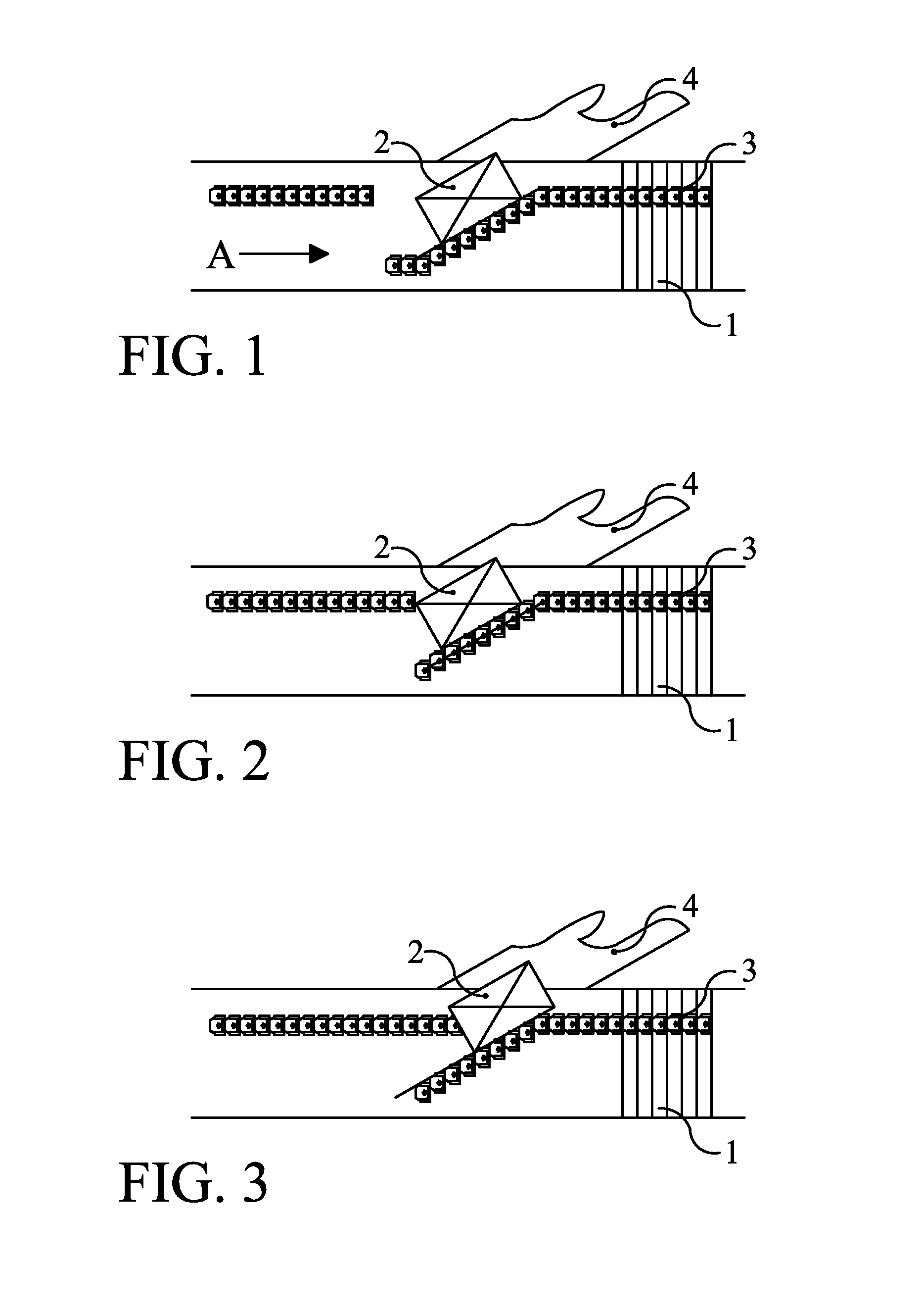
[0011]A further preferred embodiment of the invented transport device is characterized in that the guide channel forms a switch between two guide channels running in the direction of displacement, wherein the engaging surface of the switch has at the release position of the guide pin a curvature which reduces the kinetic energy of the pusher shoe in the direction transversely of the direction of displacement of the objects. A relatively low-noise operation of the device is hereby obtained. Due to mass inertia a pusher shoe will generally “shoot” to the side of the moving track at a switch, wherein it comes to a stop when it arrives against the side. This produces noise nuisance. Owing to the above described feature the pusher shoe is diverted more strongly in the direction of displacement of the objects, whereby the latter come to lie against the side with less force, or do not do so at all.
[0012]Great forces generally occur during switching from one guide channel to another guide channel. In order to prevent wear occurring and to also ensure that noise nuisance is prevented as far as possible, at least a part of the switches is preferably manufactured from a wear-resistant plastic, such as for instance polyolefins, preferably with a high-density, and / or polyamides.

Problems solved by technology

The high throughput speed creates problems at these transfer locations, wherein objects are no longer transferred smoothly and possibly change position, thereby reducing the predictability.

Method used


Image

  • Transport device
  • Transport device
  • Transport device

Examples


Embodiment Construction

[0024]With reference to the figures a transport device is shown with a series of carriers 1 which run mutually parallel and only several of which are shown in FIGS. 1-3. Using an endless moving track the carriers 1 are connected to form an endless whole, on the upper surface of which objects 2 can be displaced in the direction A indicated in FIG. 1. Pusher shoes 3 are coupled to carriers 1, this such that they are shiftable relative to carriers 1 in a direction perpendicularly of direction A or, in other words, in the longitudinal direction of the carriers 1 themselves. Connecting to the sides of the transport device can be provided discharge chutes 4 (or a second transport device) and the like, using which objects 2 delivered from the transport device onto these discharge chutes 4 can be further transported. In order to enable pushing of objects 2 to a discharge chute 4 the transport device is provided at the position of such a discharge chute 4 with means with which a desired numb...


PUM


Abstract

A transport device for objects comprises a frame with a series of carriers that run mutually parallel and are pivotally coupled to an endless drivable moving track so as to enable displacement in a direction of displacement. At least some of the carriers comprise pusher shoes with guiding construction that are shiftable along the relevant carriers transversely of the direction of displacement using guide means arranged on the frame. The guiding construction comprises a guide pin with a guide body arranged thereon, wherein the guide pin comprises at least two portions of differing diameter, that the guide means comprise a guide channel in which the guide pin can engage, and that the depth of the guide channel progresses such that, at first engagement, the portion of the guide pin with the largest diameter engages in the guide channel, and with further engagement a portion with a smaller diameter.

Description

FIELD OF THE INVENTION[0001]The invention relates to a transport device for objects.BACKGROUND OF THE INVENTION[0002]Such a device is known from the Netherlands patent NL 1020825. The known device is frequently applied for the transport of objects, wherein objects resting on the moving track can be discharged laterally of the moving track at desired locations by shifting in a determined direction along the carriers a number of pusher shoes which push the relevant object from the moving track transversely of the direction of displacement. In this manner the objects can for instance be pushed away laterally onto another moving track, whereby the objects, for instance parcel post, can be sorted.[0003]The increasing quantity of objects for sorting has resulted in a need to further increase the capacity of the known device so that more objects can be sorted per unit of time. With the known device the maximum attainable throughput speed has practically already been achieved. At a typical ...

Claims


Application Information

Patent Timeline
Patent Type & Authority Patents(United States)
IPC IPC(8): B65G47/46E04B7/22E04D3/38E04D13/16
CPCB65G47/844E04D13/16E04D3/38E04B7/22
Inventor VLUG, CASPER HERMANUS GERARDUS
Owner VAN RIET EQUIP
Why Eureka
Try Eureka