Rotary electric shaver head

An electric shaver, rotary technology, applied in metal processing and other directions, can solve the problems affecting shaving comfort and shaving effect, achieve better shaving effect, increase structural rigidity, and reduce volume

Inactive Publication Date: 2010-01-06
杨新胜 +2
View PDF5 Cites 0 Cited by
  • Summary
  • Abstract
  • Description
  • Claims
  • Application Information

AI Technical Summary

Problems solved by technology

[0004] But the rotary electric shaver head of above-mentioned structure also has its limitation, and the distance H between two blade net supports 1 changes greatly when its swinging position 9 and initial position 8, will affect the comfort level and shaving when shaving like this. beard effect

Method used


Image

  • Rotary electric shaver head
  • Rotary electric shaver head
  • Rotary electric shaver head

Examples


Embodiment Construction

[0017] The present invention will be further described in detail below in conjunction with the accompanying drawings and embodiments.

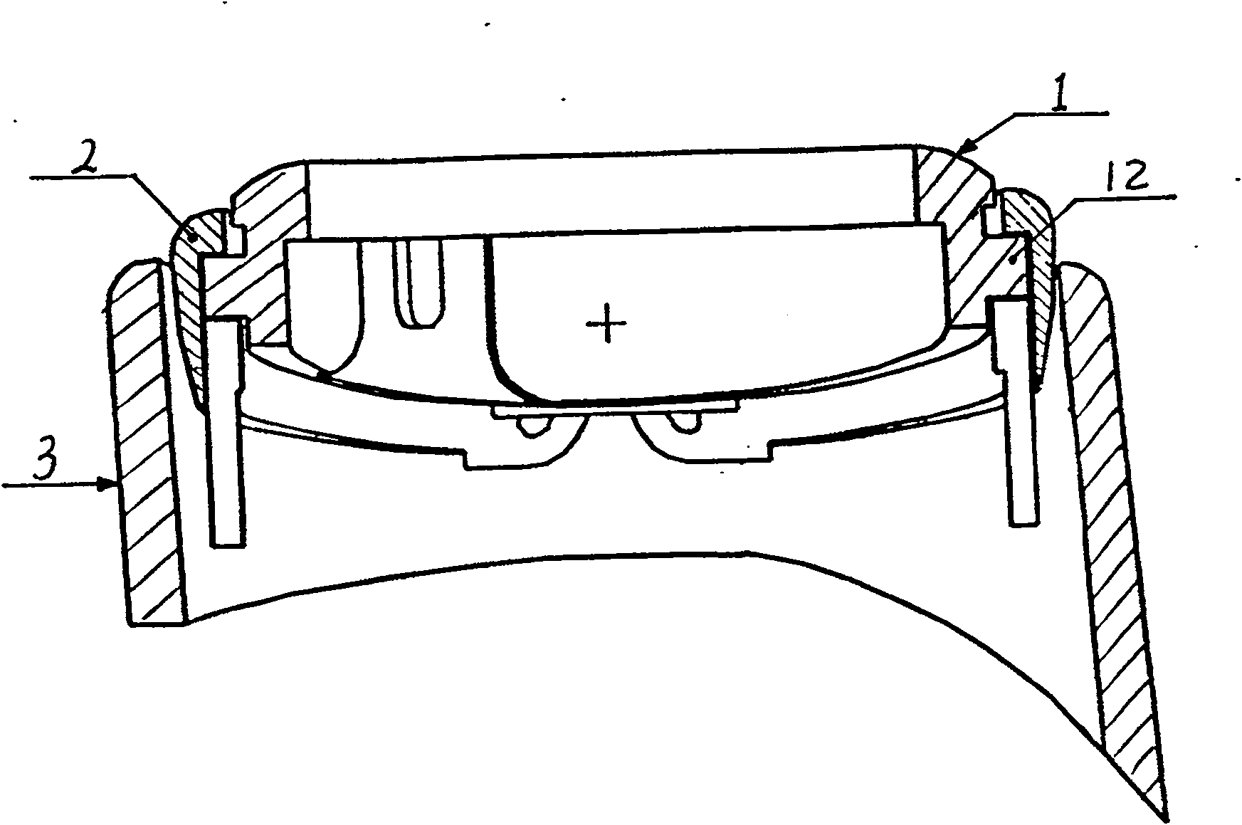
[0018] like figure 2 As shown, the rotary electric shaver head includes three parts: a knife net bracket 1 , a bracket bracket 2 , and a knife head shell 3 .

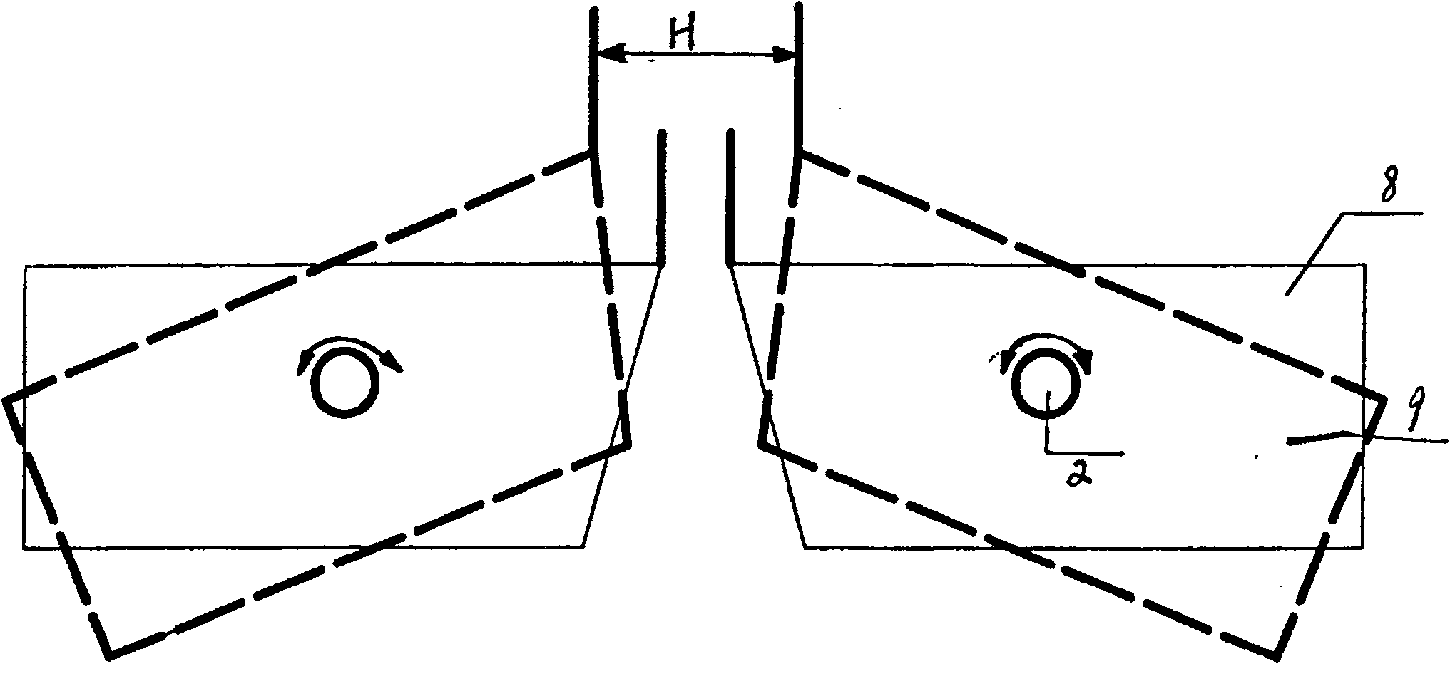
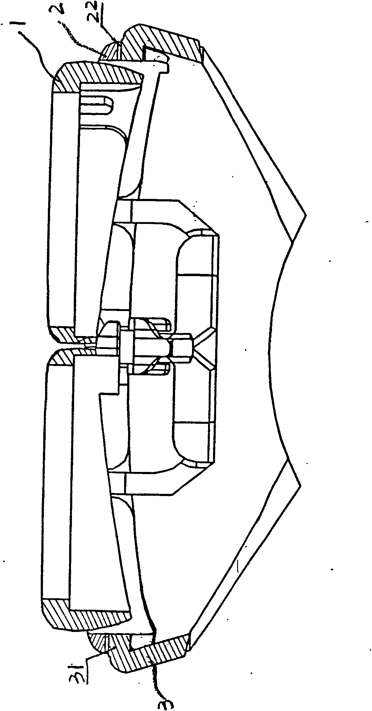
[0019] The uppermost layer is the knife net support 1, on which the knife net is installed, and is connected with the envelope surface groove 21 of the shaft 12 on the support support frame 2 by the shaft 12 on the knife net support 1, see figure 2 , image 3 , so the knife net bracket 1 and the bracket support frame 2 can move left and right while swinging left and right, and the distance H between the two knife net brackets 1 remains unchanged at the swing position 9 and the initial position 8, see Figure 4 .

[0020] The second layer structure is the bracket support frame 2, which is connected to the first layer of knife net support 1 through the envelope surface rotating shaft...


PUM


Abstract

The rotary electric shaver head includes shaver net racks, one rack support connected to the shaver net rack through one rotation shaft, and one shaver head housing connected to the rack support. The present invention has the advantages of unchanged distance between two shaver net racks, comfortable shaving, good shaving effect, small size, high structure rigidity and good look.

Description

technical field [0001] The invention relates to a rotary electric shaver head. Background technique [0002] Since the invention of the rotary electric shaver, it has been more than 100 years. Due to its safety, convenience and comfort, it has been favored by more and more people. Its structure has changed from flat blades to circular arcs. Shaped blades, from single-layer blades to multi-layer blades, from fixed double-head structure to one-dimensional swingable double-head structure, from fixed three-head structure to one-dimensional swingable three-head structure, from dry batteries to rechargeable batteries, from charging display Up to the battery capacity shows, improving the performance of the rotary electric shaver time and time again. [0003] The existing rotary electric shaver head adopts the knife net bracket to be connected with the knife shell pivot 2, see figure 1 , Can be relatively rotated between the knife net support 1 and the knife shell, can adjust the ...

Claims


Application Information

Patent Timeline
Patent Type & Authority Patents(China)
IPC IPC(8): B26B19/14B26B19/28
Inventor 杨新胜钟树平李妮
Owner 杨新胜
Why Eureka
Try Eureka