Fuel pump configuring structure of vehicle

A configuration structure and fuel pump technology, applied to bicycle accessories, combustion engines, internal combustion piston engines, etc., can solve the problems of fuel pump configuration freedom and design freedom restrictions, to increase configuration freedom and design freedom, improve The effect on drivability

Active Publication Date: 2010-01-06
HONDA MOTOR CO LTD
View PDF5 Cites 0 Cited by
  • Summary
  • Abstract
  • Description
  • Claims
  • Application Information

AI Technical Summary

Problems solved by technology

[0007] Therefore, the freedom of arrangement and design of the fuel pump is limited

Method used


Image

  • Fuel pump configuring structure of vehicle
  • Fuel pump configuring structure of vehicle
  • Fuel pump configuring structure of vehicle

Examples


Embodiment Construction

[0037] The best mode for carrying out the present invention will be described below with reference to the drawings. In addition, drawing is a figure seen along the direction of the symbol in a figure.

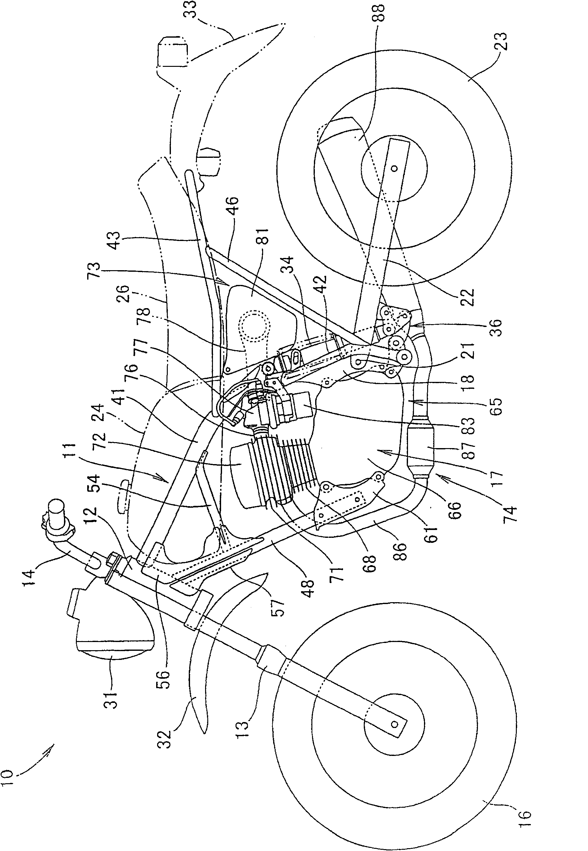
[0038] figure 1 It is a side view of a vehicle to which the fuel pump arrangement structure of the present invention is applied. The vehicle 10 is a two-wheeled motor vehicle, which is configured to have a body frame 11 and to freely steer on a head pipe 12 constituting the front end of the body frame 11. The installed front fork 13, the handle 14 installed on the top of the front fork 13, the front wheel 16 installed in the bottom of the front fork 13, the engine 17 arranged on the inside of the vehicle body frame 11, and the engine 17 that is arranged on the vehicle body frame 11. A pair of left and right pivot plates 18, 18 (only the symbol 18 on the paper side) at the rear lower part of the rear part of the pivot 21 on the pivot 21, a swing arm 22 that is freely swingable...


PUM


Abstract

The present invention relates to a fuel pump configuring structure of a vehicle which can increase the configuration freedom and designing freedom of the fuel pump. The fuel pump configuration structure is that in the vehicle a main bicycle frame (41) is arranged along the vehicle body center line (110) which extends from the center of the vehicle width direction to front and back, and the upper part of the main vehicle frame (41) is arranged with a fuel tank (24) which is additionally integrated with the fuel pump (83), the engine (17) is arranged at the lower part of the main vehicle frame (41) and the throttle valve body (77) is arranged at the back of the engine (17), wherein, seeing from the plane the fuel pump (83) and is arranged at the side opposite to the throttle valve body (77) clamping the main vehicle frame (41) and is parallel arranged with the throttle valve body (70) in the vehicle width direction.

Description

technical field [0001] The present invention relates to improvement of a fuel pump arrangement structure of a vehicle. Background technique [0002] As a conventional vehicle fuel pump arrangement structure, a structure in which a fuel pump is arranged between a pair of left and right frame members extending from a head pipe toward the rear of the vehicle is known (for example, refer to Patent Document 1). [0003] Patent Document 1: (Japanese) Unexamined Patent Publication No. 2005-96504 [0004] The following describes the patent document 1 figure 2 and image 3 . [0005] A two-wheeled motor vehicle has a pair of left and right main pipes MP extending obliquely downward from the head pipe Fh rearward, a pair of left and right pivot plates 5 connected to the rear ends of the main pipes MP, and a pair of left and right bottom pipes extending substantially downward from the head pipe Fh. A body frame F of the bushing DT, on which the engine E is mounted, and a throttle b...

Claims


Application Information

Patent Timeline
Patent Type & Authority Patents(China)
IPC IPC(8): B62J37/00
CPCY02T10/123Y02T10/12
Inventor 清野浩司
Owner HONDA MOTOR CO LTD
Why Eureka
Try Eureka