Sanitary outlet unit

A drainage device and sanitation technology, which can be used in water supply devices, indoor sanitary pipeline devices, spray devices, etc., and can solve problems such as leaks

Active Publication Date: 2010-01-06
NEOPERL
View PDF9 Cites 0 Cited by
  • Summary
  • Abstract
  • Description
  • Claims
  • Application Information

AI Technical Summary

Problems solved by technology

With this pull-out swing arm, it is not possible to screw a conventional jet regulator on the discharge...

Method used


Image

  • Sanitary outlet unit
  • Sanitary outlet unit
  • Sanitary outlet unit

Examples


Embodiment Construction

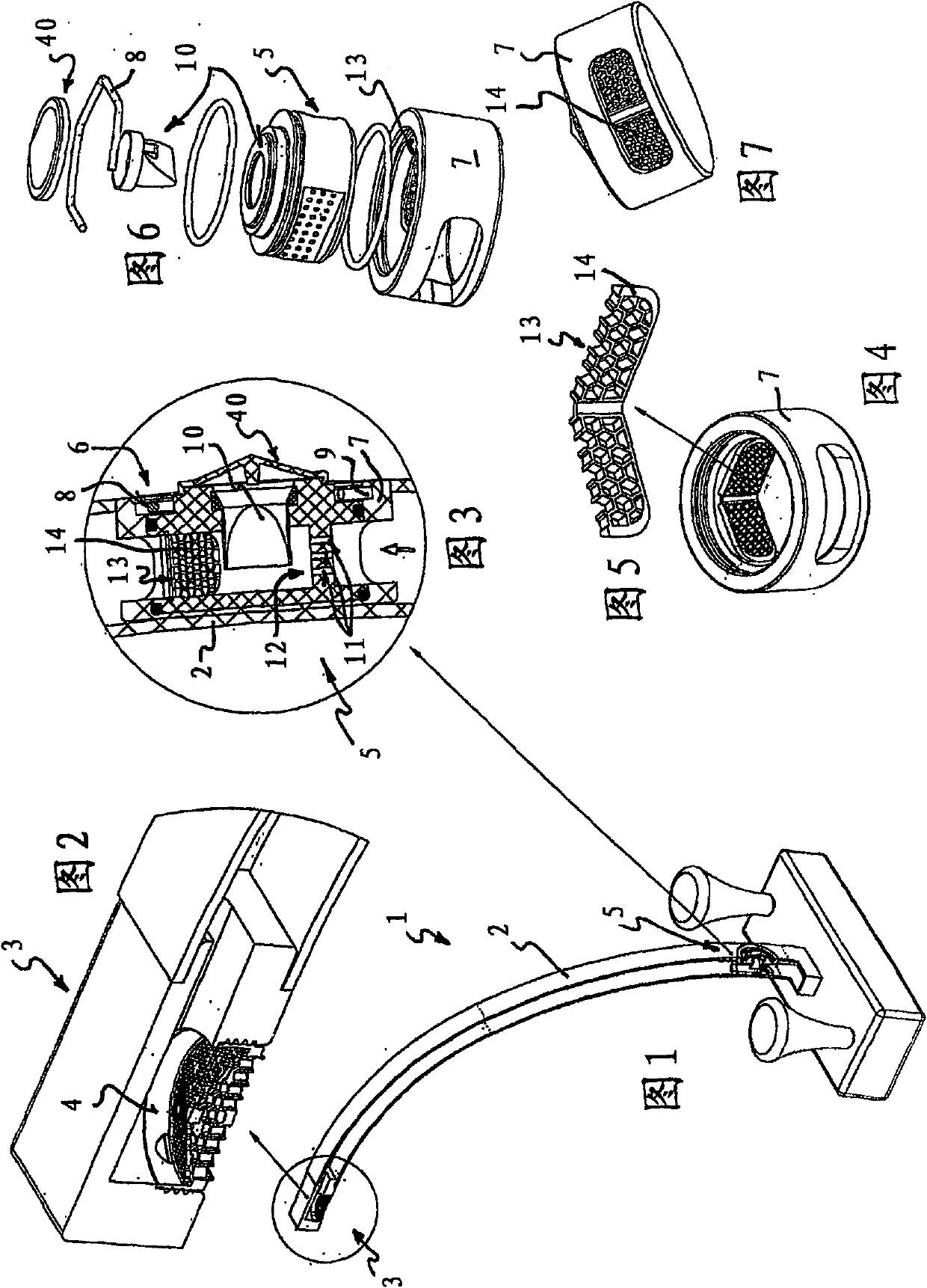
[0072] Figures 1 to 7 Different views of a sanitary drainage device 1 are shown in . The drain device 1 has a drain fitting 2 which has a figure 2 The jet regulator 4 shown in , which should form the discharged water jet evenly. In order to also be able to aerate the water jet and to generate a bead-softened water jet, an aeration device 5 is provided.

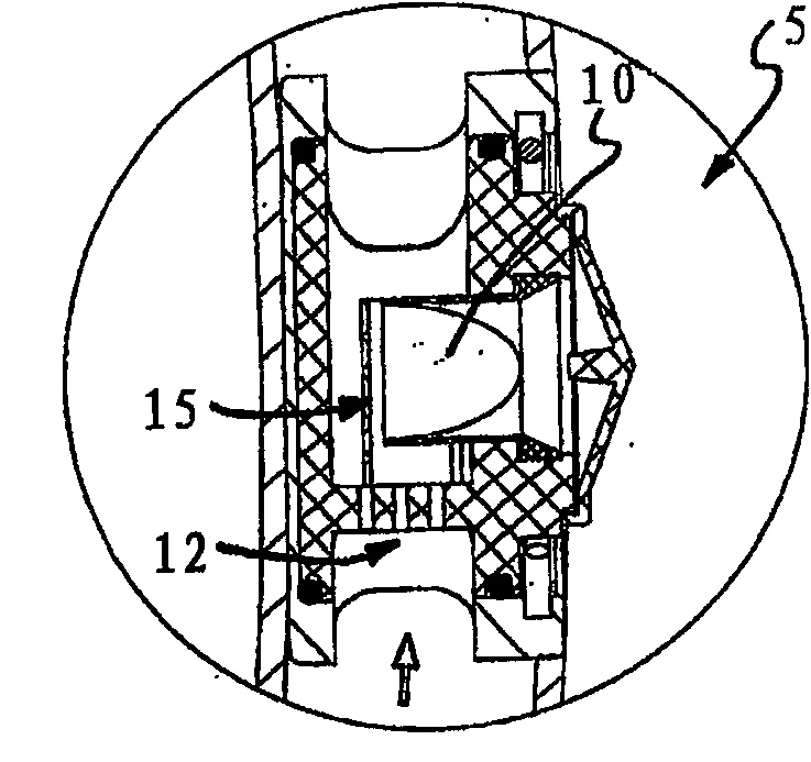
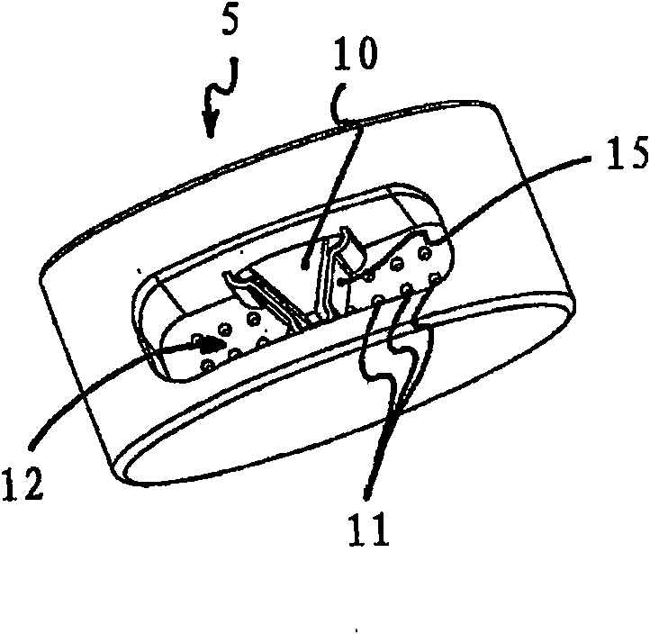
[0073] Depend on Figures 1 to 3 It becomes clear from the comparison that the aeration device 5 is arranged in the drain fitting 2 separately from the jet regulator 4 . In the fitting housing of the drain fitting 2 , for this purpose upstream at a distance from the drain opening 3 and the jet regulator 4 there, an insertion opening 6 which leads into the fitting inner cross section is provided laterally on the fitting housing. The insertion opening 6 leads to a sleeve-shaped sleeve or cylindrical recess 7 provided in the fitting housing, which is designed as a thin-walled plate structure and is designed to be open on th...


PUM


Abstract

The invention relates to a sanitary outlet unit (1), comprising a outlet fitting (2), with a flow regulator (4) in the region of the water outlet (3) thereof, whereby an aeration device is provided for aeration of the water flow. Said outlet unit (1) is characterized in that the aeration device (5) is provided in the outlet fitting (2) and/or in at least one water line leading to the outlet fitting (2) separately from the flow regulator (4). By means of the spatial separation of the functions of flow shaping or water outlet and aeration of the water flow, there are many possible embodiments for optionally providing the water outlet (3) of the sanitary outlet unit (1) with an extremely thin embodiment.

Description

technical field [0001] The invention relates to a sanitary drainage device. Background technique [0002] Various jet regulators are known which aerate the water jet emerging from a sanitary fitting and are intended to form a uniform bead-shaped softened water jet. For this purpose, the above-mentioned jet regulator has in its jet regulator housing a jet splitter, usually in the form of a perforated plate, behind which a homogenizing device and possibly a flow straightening device are connected. The jet regulator housing of the aforementioned jet regulator has an aeration hole in the region of the homogenization device, which serves as an aeration device for aerating the water jet which is temporarily divided into individual jets by means of a jet splitter (cf. DE-A-3000799) . The above-mentioned jet regulator housing is installed in a drain nozzle with its jet regulator housing, and can be detachably fixed on the accessory drain port by means of a threaded connection. ...

Claims


Application Information

Patent Timeline
IPC IPC(8): E03C1/084
CPCE03C1/0404E03C1/084B05B7/0425
Inventor O·登茨勒
Owner NEOPERL
Why Eureka
Try Eureka