
Tool monitoring device

A technology of equipment and tools, applied in the field of tool monitoring equipment, can solve the problem of no tool usage time statistics

Inactive Publication Date: 2010-01-20
FIVE SIDES IND
View PDF3 Cites 0 Cited by
  • Summary
  • Abstract
  • Description
  • Claims
  • Application Information

AI Technical Summary

Problems solved by technology

[0005] A common problem with such preventive maintenance is that power tools are typically returned for maintenance based on set intervals of use, such as 6 months, during which there is no real Accurately count the actual usage time of tools

Method used


Image

  • Tool monitoring device
  • Tool monitoring device
  • Tool monitoring device

Examples


Embodiment Construction

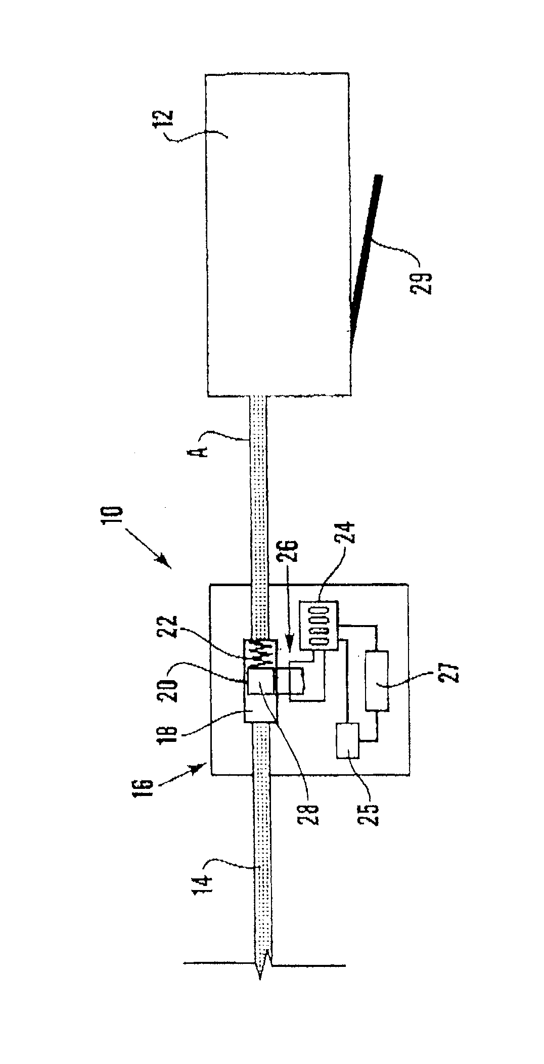
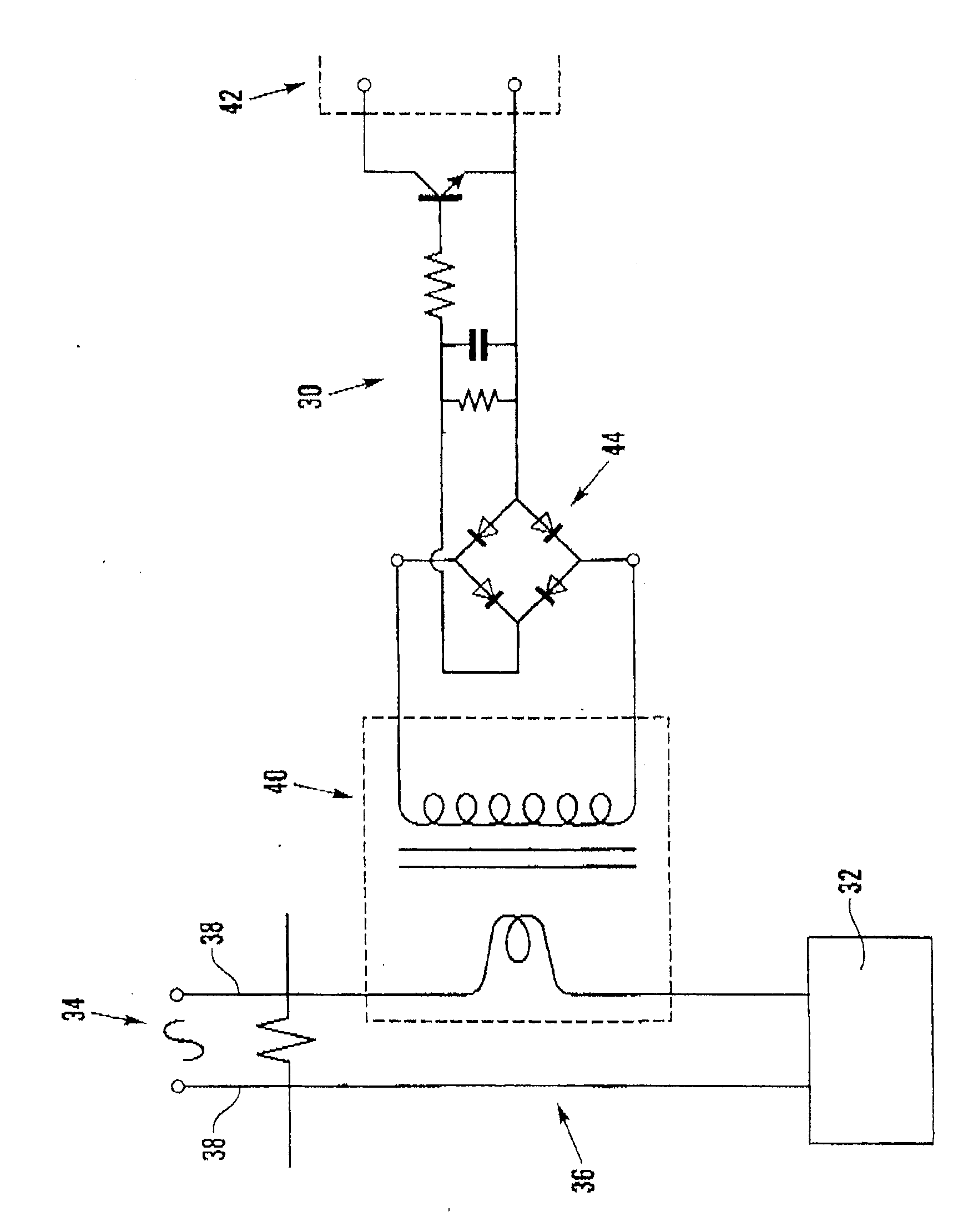
[0035] refer to figure 1 with 2 , devices according to a first embodiment of the invention are all indicated at 10 . The figure shows a device 10 for a power tool 12 , which in this embodiment is a pneumatic drill. The tool 12 is connected to a pneumatic source 13 such as compressed air (compressed air here) through a dedicated supply line 14, so as to provide working power to the drill 12, that is, to drive the drill.

[0036] The device 10 consists of a dedicated unit or housing having an input 17 connectable to a power source 13 and an output 19 connectable to a power tool 12 . The device has an internal passage mechanism 21 which connects the input and output 17 , 19 together so that when the power source 13 is connected to the input 17 compressed gas passes through the passage mechanism 21 to the power tool 12 . The housing 16 is preferably adjacent the drill 12 and away from the compressed air source 13 so as to be easily visible to the tool operator when in use.

[...


PUM


Abstract

A device for monitoring the usage of a pneumatically or electrically operated power tool comprises a sensor for sensing the supply of the pneumatic or electrical power from a source to the tool and monitoring means responsive to the sensor for recording the time elapsed during the supply of power.

Description

technical field [0001] The invention relates to a device for monitoring the use of a power tool. Background technique [0002] The safe use of power tools, such as pneumatic drills, on the job site is very important to health and safety. This is especially true when, if not properly monitored, power tools can transmit vibrations to the user's body, leading to debilitating injuries such as vibration white finger. [0003] The level of vibration a user experiences from a particular power tool depends on a variety of factors, including whether the tool or a workpiece on which the tool is used is properly supported or mounted during operation of the tool. A power tool's maintenance records can also have a significant impact on the level of vibration experienced during use of the tool. Some power tools vibrate after extended use two to three times higher than when the tool was first manufactured, or in a freshly repaired condition where it has only recently been serviced or rep...

Claims


Application Information

Patent Timeline
Patent Type & Authority Patents(China)
IPC IPC(8): G07C3/10G07C3/04B25D17/00
CPCG07C3/10G07C3/04
Inventor 迈克尔·J·琼斯安东尼·詹特马修·巴特勒
Owner FIVE SIDES IND
Learn More