Monitoring method and monitoring device for laser equipment

A technology of laser equipment and monitoring devices, which is applied to the identification of patterns in signals, medical care resources or facilities, instruments, etc., and can solve problems such as the inability to report the use of equipment, the lack of networking functions of laser equipment, and the inability to meet market demand.

Pending Publication Date: 2022-05-06
海南新氧医疗科技有限公司
View PDF0 Cites 0 Cited by
  • Summary
  • Abstract
  • Description
  • Claims
  • Application Information

AI Technical Summary

Problems solved by technology

[0002] At present, laser equipment used for beauty treatment in the field of medical beauty is more and more widely used. Due to the relatively high price of equipment, the use mode of renting and selling is usually adopted. In this use mode, there will be monitoring laser equipment Usage requirements, but since this kind of laser equipment usually does not have networking capabilities, it is impossible to report the usage of the equipment
[0003] If you add a networking function to the laser device, you need to change the device itself, but this kind of laser device is a medical device, and the certificate application period for adding the networking function is relatively long, which cannot meet the market demand.

Method used


Image

  • Monitoring method and monitoring device for laser equipment
  • Monitoring method and monitoring device for laser equipment
  • Monitoring method and monitoring device for laser equipment

Examples


Embodiment Construction

[0035] The following will clearly and completely describe the technical solutions in the embodiments of the present invention with reference to the accompanying drawings in the embodiments of the present invention. Obviously, the described embodiments are only part of the embodiments of the present invention, not all of them. Based on the embodiments of the present invention, all other embodiments obtained by persons of ordinary skill in the art without creative efforts fall within the protection scope of the present invention.

[0036] It should be noted that all directional indications (such as up, down, left, right, front, back...) in the embodiments of the present invention are only used to explain the relationship between the components in a certain posture (as shown in the accompanying drawings). Relative positional relationship, movement conditions, etc., if the specific posture changes, the directional indication will also change accordingly.

[0037] In addition, in t...


PUM


Abstract

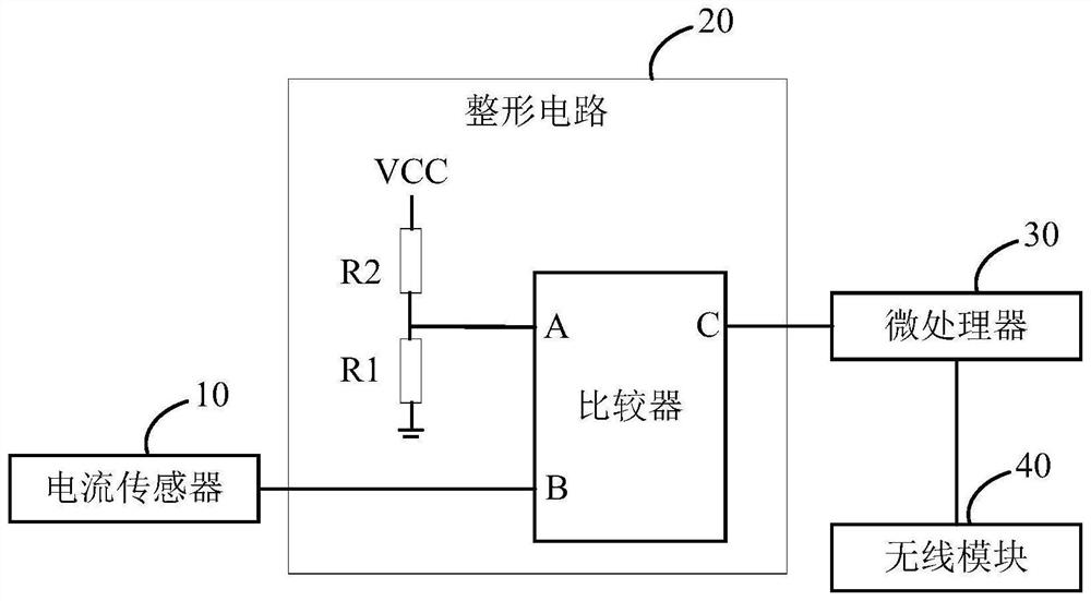
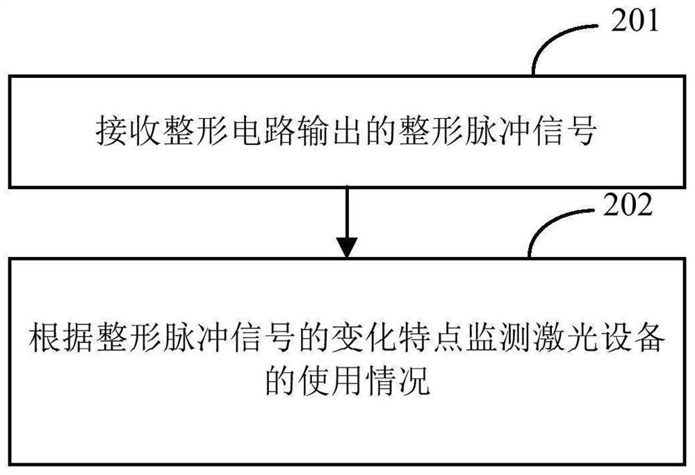
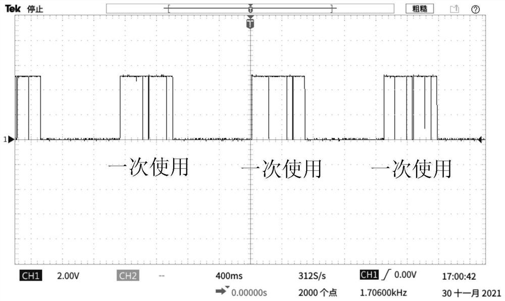
The invention discloses a monitoring method and a monitoring device for laser equipment, and the monitoring device comprises a current sensor which is provided with a threading hole, and a measured wire of the laser equipment passes through the threading hole; the tested wire is used for transmitting charging and discharging current of a front-end capacitor on the laser equipment; the shaping circuit is connected with the current sensor; and the microprocessor is connected with the shaping circuit. Before laser equipment emits light, a front-end capacitor on the equipment needs to be charged, and a power supply line for transmitting charging and discharging current of the front-end capacitor on the laser equipment passes through a threading hole of a current sensor, so that the current sensor generates a sensing signal after sensing alternating current; and after being shaped by the shaping circuit, the signals are output to the microprocessor for analysis and monitoring. In this way, on the premise that the laser equipment is not changed, according to the use characteristics of the laser equipment, the use condition of the laser equipment can be monitored through the monitoring device, and therefore the market use requirement is met.

Description

technical field [0001] The invention relates to the technical field of equipment monitoring, in particular to a monitoring method and a monitoring device for laser equipment. Background technique [0002] At present, laser equipment used for beauty treatment in the field of medical beauty is more and more widely used. Due to the relatively high price of equipment, the use mode of renting and selling is usually adopted. In this use mode, there will be monitoring laser equipment However, since this kind of laser equipment usually does not have networking capabilities, it is impossible to report the usage of the equipment. [0003] If the networking function is added to the laser device, the device itself needs to be changed, but this kind of laser device belongs to medical equipment, and the certificate application period for adding the networking function is relatively long, which cannot meet the market demand. Contents of the invention [0004] The purpose of the present ...

Claims


Application Information

Patent Timeline
Patent Type & Authority Applications(China)
IPC IPC(8): G06K9/00G16H40/20
CPCG16H40/20G06F2218/02G06F2218/08
Inventor 侍伟科皮明强李天府李格周江
Owner 海南新氧医疗科技有限公司
Why Eureka
Try Eureka