Intelligent pen with low ink warning function
A functional and intelligent technology, applied to ink pens, printing and writing utensils with ink storage tubes in the pen barrel, can solve the problems affecting normal use, inconvenient to carry ink, water absorption, etc.
- Summary
- Abstract
- Description
- Claims
- Application Information
AI Technical Summary
Problems solved by technology
Method used
Image
Examples
Embodiment 1
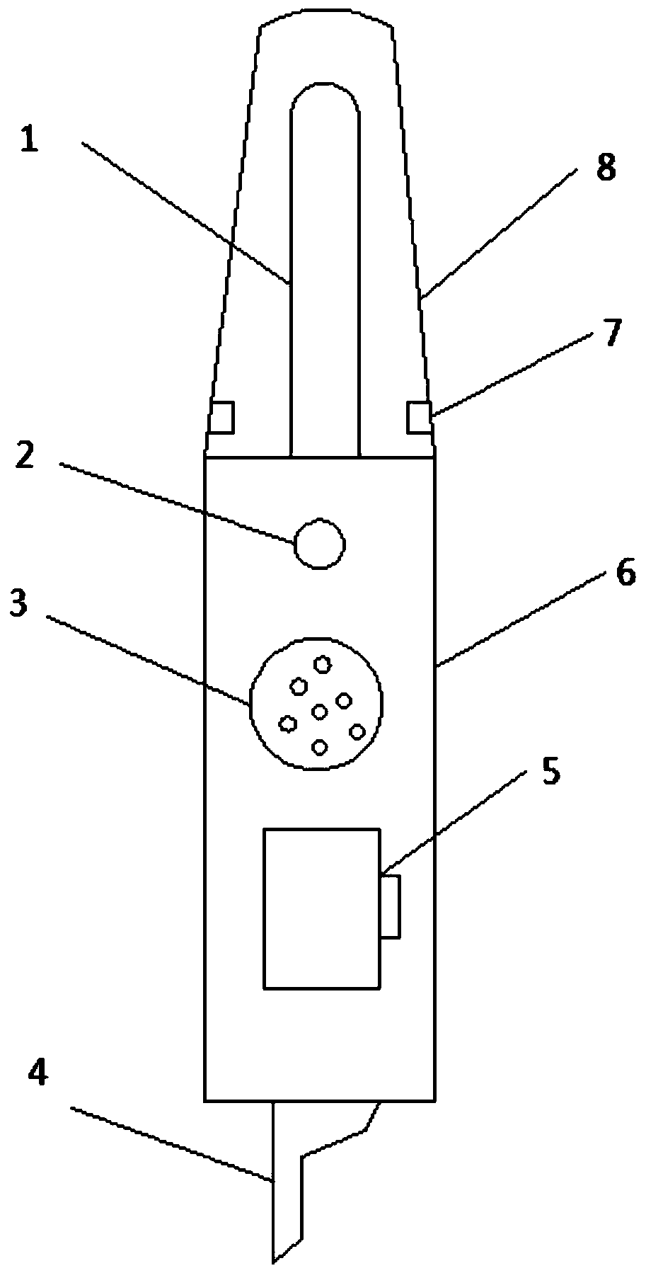
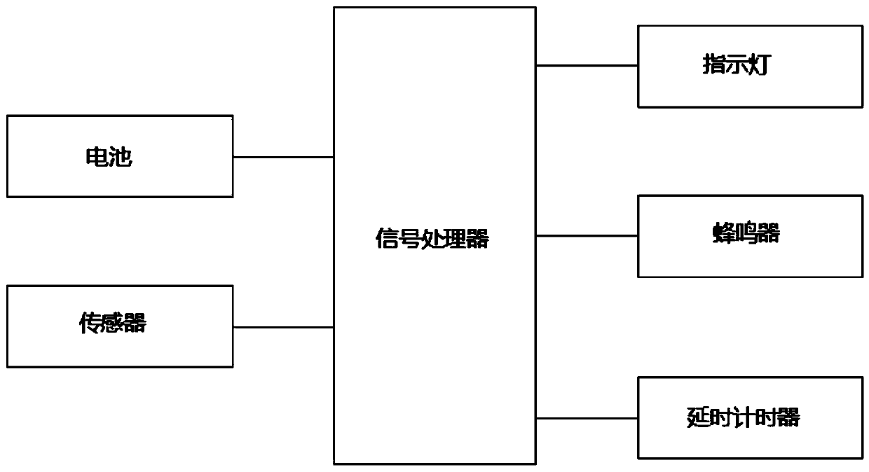
[0019] Example 1: See Figure 1-3 , a smart pen with an ink shortage alarm function, comprising a pen holder 6 and a pen cover 8, the pen holder 6 and the pen cover 8 are flexibly connected, the bottom of the pen holder 6 is provided with a nib 4, and the top of the pen holder 6 is provided with a storage When the ink tube 1, the penholder 6 and the pen cover 8 are connected, the ink storage tube 1 is located inside the pen cover 8, and the inside of the pen cover 8 is provided with a sensor 7 for detecting the ink content in the ink storage tube 1. The penholder 6 is also provided with an indicator light 2 for light prompting. The pen holder 6 is also provided with a buzzer 3 for light prompting. The pen holder 6 is also provided with a battery cover 5, and the inside of the battery cover 5 is provided with a battery. The battery is a micro button cell. Small in size, it will not increase the excessive weight and volume of the pen, and the inside of the pen holder 6 is als...
Embodiment 2
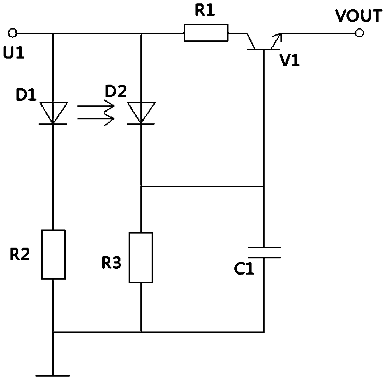
[0020] Embodiment 2, on the basis of embodiment 1, as image 3 As shown, the sensor includes diode D1, diode D2, triode V1 and resistor R1, the anode of diode D1 is connected to the anode of diode D2, resistor R1 and power supply U1, the cathode of diode D1 is connected to resistor R2, the cathode of diode D2 is connected to capacitor C1, resistor R3 and the base of the transistor V1, the other end of the resistor R1 is connected to the relay of the transistor V1, the emitter of the transistor V1 is connected to the sensor signal output terminal VOUT, the other end of the resistor R2 is connected to the other end of the resistor R3, the other end of the capacitor C1 and ground . Diode D1 and diode D2, one is a light-emitting diode and the other is a photosensitive diode. Diode D1 and diode D2 form a through-beam sensor. The ink storage tube 1 is located between the optical path of the diode D1 and the diode D2. , the optical path of diode D1 and diode D2 is blocked, diode D1 ...
PUM
 Abstract
Description
Claims
Application Information
 - R&D
- Intellectual Property
- Life Sciences
- Materials
- Tech Scout
- Unparalleled Data Quality
- Higher Quality Content
- 60% Fewer Hallucinations
Browse by: Latest US Patents, China's latest patents, Technical Efficacy Thesaurus, Application Domain, Technology Topic, Popular Technical Reports.
© 2025 PatSnap. All rights reserved.Legal|Privacy policy|Modern Slavery Act Transparency Statement|Sitemap|About US| Contact US: help@patsnap.com


