Sliding type joint angle

A connection angle and sliding technology, applied in windows/doors, building components, buildings, etc., can solve the problems of difficult use of profile frames, poor connection quality, easy to disengage, etc., and achieve simple structure, low cost, firm and safe connection Effect

Inactive Publication Date: 2007-07-18
张文奇
View PDF0 Cites 4 Cited by
  • Summary
  • Abstract
  • Description
  • Claims
  • Application Information

AI Technical Summary

Problems solved by technology

[0002] With the improvement of people's living standards and the accelerated development of the economy, various decorations have become hot spots. At present, the decoration of homes and public places is not only pursuing high-end and beautiful decoration, but also pursuing safe and anti-theft decoration materials and decoration methods. So far, the butt joints of profile frames for installing doors and windows are often connected by welding and bonding. This connection method is easy to disengage. It is difficult to reuse the frame after being disassembled by the connecting parts

Method used


Image

  • Sliding type joint angle

Examples


Embodiment Construction

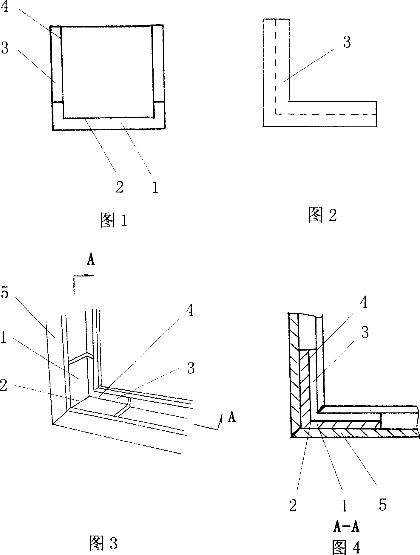
[0015] As shown in Figure 1 and Figure 2, the sliding connection angle is folded into 90 degrees by the flat rectangular body 1 and the crease line 2 at the set position in the length direction of the body 1, and the two sides of the body 1 in the width direction are respectively provided with connecting parts 3 composition.

[0016] The connecting part 3 is formed by folding 90 degrees toward the main body 1 at the crease line 4 at a set position on the main body 1 .

[0017] Each top end of the connecting portion 3 is respectively provided with rounded corners.

[0018] When specifically using the present invention to install the connected parts 5, as shown in Figure 3 and Figure 4, it is only necessary to process the butt joints of the connected parts 5 into 90-degree slopes, and then insert the connected parts 5 into 90-degree slopes. On the body 1, quick installation and positioning are realized.


PUM


Abstract

The present invention relates to connecting pieces, and is especially one kind of sliding connecting angle for connecting section material of anti-theft door, anti-theft window, etc. The sliding connecting angle consists of one flat rectangular body and connecting units set on two sides of the body. The sliding connecting angle may be fast located, and has the advantages of convenient installation, high reliability, simple structure, high strength, capacity of reusing the disassembled connected part, etc.

Description

technical field [0001] The invention relates to a connecting piece, in particular to a sliding connection angle used for connecting profiles such as anti-theft doors and anti-theft windows. Background technique [0002] With the improvement of people's living standards and the accelerated development of the economy, various decorations have become hot spots. At present, the decoration of homes and public places is not only pursuing high-end and beautiful decoration, but also pursuing safe and anti-theft decoration materials and decoration methods. So far, the butt joints of profile frames for installing doors and windows are often connected by welding and bonding. This connection method is easy to disengage. It is difficult to reuse the frame etc. after being disassembled by the connecting parts. Contents of the invention [0003] The present invention is proposed in response to the above-mentioned problems, and its purpose is to provide a device suitable for various envi...

Claims


Application Information

Patent Timeline
Patent Type & Authority Applications(China)
IPC IPC(8): E06B3/968
Inventor 张文奇
Owner 张文奇
Why Eureka
Try Eureka